Does T6 Quenching Break a 0.02 mm Assembly Face?
T6 quenching does not break a 0.02 mm assembly face by itself. The quench moves a 1.5 mm ADC12 frame past that band, and the route brings it back: post-machining of castings straightens the frame after T6, then CNC machining cuts face and holes in one setup. Die casting machining tolerance comes from that order.
What Quenching Does to a 1.5 mm Frame
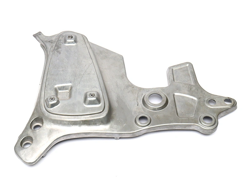
T6 for ADC12 holds the frame at a solution temperature of 490–510 °C, quenches it, and ages it. The plant confirms whether a frame can take T6 before the drawing is released. A frame with a 1.5 mm wall and thicker joint bosses does not cool at one rate. The wall cools first, the boss lags and keeps contracting after the wall is set. The frame twists and bows as a result, and the joint seats move past the ±0.02 mm design target.
The wall is 1.5 mm, the flatness band 0.03 mm, the hole position ±0.02 mm. A 0.03 mm bow on the seat is a fiftieth of the wall thickness, and the holes drilled from it follow the bow. Bolts then pull the face down, and the holes move with it.
Straightening Sits Between T6 and CNC
The route orders the steps: vacuum die casting, gate removal, T6, straightening, CNC. Straightening is a press step on the quenched frame, measured against the same pads the cut will use, so every seat still has metal to cut. It sets the bulk shape; the face still has to be machined to the target.
Skip it and the cutter does the straightening. A bowed frame gets clamped flat in the fixture, the face is cut, and the part springs on release. Removing stock releases stress as well, so a face that read inside ±0.02 mm on the machine can move after the clamps open.
Straightening cannot repair a datum. Straighten against the wrong face and the seats stay consistent with each other, in the wrong place. The press step carries risk: a cold bend on a quenched wall can mark a surface or start a crack at a fillet, so it is measured, not forced.
Where the 0.02 mm Comes From
The ±0.02 mm assembly face and the ±0.02 mm hole position are design targets, and both rest on three decisions: the datum face, the stock the cut leaves, and the setups the part sees.
The datum has to be a machined pad. Locate on the 1.5 mm as-cast wall and the cut inherits draft, skin and casting scatter from a surface nobody measured. From a machined pad, face and holes are cut in one setup, so the hole pattern follows the face instead of its own alignment.
A second setup spends the re-location error before the cutter adds anything, and on a thin-wall frame that error can exceed the band it is charged to.
Clamping a Thin Wall Without Springing It
A 1.5 mm wall moves under clamp pressure. Clamp the frame hard, cut the face, measure it in the fixture, and the reading looks good. Release the clamps and the face springs back out of tolerance, with the hole centers moving with it.
The fixture should locate on the machined pads and hold the wall under the cut on adjustable supports. Clamp force stays low, enough to seat the part and not to bend it. The CMM then aligns the way the fixture did, on the same datum, or the report describes a part the shop never made.
Where the seat joins a rigid bolted plate, a restrained check matches service. Where the seat has to sit flat before the bolts are torqued, only the free state counts.
Flatness 0.03: Free State or Clamped
Flatness is a form tolerance. ISO 1101 defines the zone an inspector measures against; whether it applies free or restrained is a drawing decision. Leave it out and two inspectors can disagree while both are right.
Every number in the table is a design target, measured on a CMM point map rather than judged by eye.
Requirement | Target (unit) | Verified by | Where in the route |
|---|---|---|---|
Assembly face | ±0.02 mm | CMM point map | Cut after straightening |
Face flatness | 0.03 mm | CMM, free or restrained | Same setup as the face |
Hole position | ±0.02 mm | CMM, same setup as the face | Drilled with the face |
Straightening | Before the cut | Press check on the datum | Between T6 and CNC |
Send the drawing with the datum pads marked, the flatness callout stating free or restrained, and straightening named between T6 and the cut. Ask for the CMM point map on the face and at the hole centers.