Post-Die Cast Finishing: How Buyers Match Deburring, Blasting, Coating and Machining
Post-die cast finishing works when every operation receives a known part condition and returns evidence that the next operation can use. A raw casting may carry gate remnants, parting-line flash, release agent, local porosity indications, machined stock and surfaces with different cosmetic or functional roles. Sending that part directly to a coating line turns unresolved casting and edge conditions into expensive finished-part rejections.
The route is not fixed for every component. A cosmetic cover, threaded enclosure and plated zinc latch may begin with similar trimming, yet their transfers differ. Thread and seal protection, controlled texture, substrate-specific preparation, datum state, coating build and environmental exposure all change the operation order.
Buyers can make the sequence auditable by defining an incoming state, output condition and hold rule for each step. The decisions begin with the raw casting, move through trimming and mechanical preparation, place CNC at the correct finish state, qualify cleaning and coating, and end with dimensional, film, appearance and packaging checks. A finish cannot hide or repair porosity, cracks or cold shuts; disposition comes before coating.

What Should Be Checked Before Post-Die Cast Finishing Starts?
Start with a casting-condition map tied to the controlled drawing. It records substrate and alloy designation, heat or material condition where relevant, gate and overflow locations, parting line, ejector witnesses, flash, machining stock and areas exposed in service. Separate visible zones from threaded, sealing, bearing, grounding, thermal-contact and fixture zones. A surface can belong to more than one group: a visible mounting rim may also control gasket compression.
Defect disposition comes before cosmetic preparation. Inspect the zones where trimming or machining could open a discontinuity, and apply the project's acceptance method for porosity indications, cracks, cold shuts, laps or damaged walls. The presence of a coating step does not relax casting integrity. Parts held for engineering review cannot be released because blasting makes the indication less visible.
Contamination also needs a source and location. Die release agent, trimming lubricant, cutting oil, fingerprints, protective oil, wet blast residue and cleaning carryover behave differently. Oil must be removed before an abrasive step that could drive or spread it across the surface. Blind holes, rib pockets and porous gate regions may retain liquid; drying and thermal exposure need evaluation against the later coating cycle.
Incoming Condition | Question Before Release | Required Evidence | Hold Trigger |
|---|---|---|---|
Substrate and casting source | Is the specified alloy/condition identified and compatible with the proposed chemistry? | Material identity and represented casting source or cavity where required | Unknown substitution or unqualified alloy/finish pairing |
Gate and parting geography | Can removal occur without entering a datum, seal, thin edge or A-zone? | Indexed removal map and residual/edge criteria | Removal boundary conflicts with a protected feature |
Casting indications | Could finishing obscure or machining open a function-relevant discontinuity? | Zone-specific visual, dimensional or other specified acceptance result | Crack, cold shut, harmful porosity indication or unresolved damage |
Oil and process residue | Where did it originate and can the planned cleaning reach it? | Source map, cleaning trial and drying condition | Unknown residue, trapped liquid or failed cleanliness evidence |
Functional/cosmetic zones | Which surfaces require build, masking, bare contact, controlled texture or dimensional protection? | Zone and mask drawings linked to datums | Ambiguous boundary or conflicting finish notes |
Service environment | What exposure, wear, electrical, thermal or appearance requirement drives the finish? | Project-specific performance and acceptance condition | Finish selected without a defined use condition |
The first handoff is complete only when the raw part is identified, unresolved defects are contained, protected zones are mapped and the removal/cleaning route has an owner. This gate prevents downstream operations from making an unacceptable casting harder to diagnose.
How Trimming and Deburring Protect Assembly and Handling
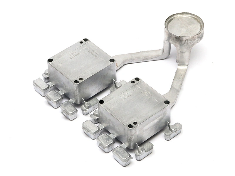
Trimming removes runners, gates, overflows and gross flash; deburring brings their residual edges and other sharp transitions to the drawing-defined condition. The objective is not to round every edge. A connector lead-in may need a controlled break, while a sealing lip, narrow rib, datum pad or visible corner may require minimal material removal. The edge map must distinguish those consequences.
Operation order moves from controlled gross removal to local cleanup and, when suitable, batch finishing. A saw, trim die or indexed cutter removes most of a gate while preserving stock for final blending. Local tools address heavy vestiges; batch finishing handles distributed light burrs only when thin features and openings survive the qualified exposure.
Assembly protection is verified at the actual interfaces. Check thread starts, connector slots, gasket lands, locating holes, clip windows and cable paths for raised metal or loose fragments. Handling protection includes sharp-edge review and clean rack contact, but safety language does not replace an edge dimension where fit or appearance depends on the result. The trimming handoff records residual height/shape, protected-pad condition, edge acceptance and loose-debris removal before blasting or machining starts.
When Tumbling, Grinding, Polishing or Blasting Is Appropriate
Mechanical methods are selected from the starting defect, geometry and required output, not from a general preference for a smooth or matte part. Tumbling can treat distributed light burrs and blend broad populations of small parts. Grinding is local and effective on gate remnants or heavy flash. Polishing is directional and can prepare a visible metal surface, but it may reveal substrate variation. Sand blasting can clean and texture accessible fields or create a controlled mechanical preparation state.
None of these methods substitutes for casting acceptance or chemical cleanliness. Abrasion can smear metal, embed media, round edges and alter dimensions. Blasting over oil can spread contamination; polishing cannot repair a crack; aggressive grinding can open or enlarge a near-surface discontinuity. Trial parts need the worst gate condition, thinnest exposed feature, smallest relevant opening and most visible field.
Mechanical Method | Appropriate Starting Condition | Useful Output | Main Risk | Handoff Criteria |
|---|---|---|---|---|
Tumbling | Distributed light burrs; geometry tolerates controlled part/media contact | Consistent deburring or blending across a batch | Thin-edge rounding, part collision, media entrapment | Indexed edge limits, no trapped media, stable dimensions and clean surface |
Local grinding | Heavy gate witness or localized flash with accessible tool path | Residual brought into its local contour/height requirement | Gouge, heat tint, low spot, exposed discontinuity or datum damage | Contour, residual, adjacent wall and surface-damage checks pass |
Polishing | Defined visible metal field with adequate stock and controlled direction | Specified luster or directional surface condition | Waviness, rounded detail, nonuniform appearance from substrate variation | Master comparison, geometry and residue requirements are met |
Blasting | Clean accessible surface needing controlled texture or mechanical preparation | Uniform prepared field within the qualified line of sight | Edge erosion, peening, shadowing, embedded media or masked-line step | Texture reference, edge/feature checks, media removal and cleanliness pass |
The mechanical-preparation handoff identifies the method, media or tool family, protected features, accepted reference surface and cleaning requirement. A visually uniform part remains on hold if media occupies a bore, a datum was rounded or the surface fails the next pretreatment's cleanliness condition.
Should CNC Machining Happen Before or After Surface Finishing?
CNC machining normally precedes coating when it creates threads, precision bores, sealing faces or other features that must exist before masking and final dimensional inspection. Finishing before selective machining can make sense when the final cut intentionally exposes a bare electrical contact, controlled mating pad or crisp uncoated field. A split route may rough-machine, finish and then make a qualified final cut, but every extra transfer adds edge, contamination and corrosion-exposure questions.
The decision follows the final feature state. Coating buildup can reduce bore diameter, change thread fit and create a shoulder beside a mask. Machining after coating can chip or lift the film, load a cutter, contaminate coolant and expose unprotected substrate. The post-machining route needs a clear answer for datums, masking, film allowance, final bare surfaces and reinspection.
Sequence Choice | Use When | Critical Control | Release to Next Step |
|---|---|---|---|
Trim/deburr, then machine, then finish | Threads, bores, seals and finished datums must be created before masking | Machining-fluid removal, burr-free exits and mask references | Dimensions pass in pre-coat state; all coat-free zones are defined |
Mechanical preparation, then machine, then coat | Gate/texture cleanup is needed before reliable fixturing or cosmetic coating | Protect raw fixture contacts and clean media before machining | Fixture state, machined features and contamination checks pass |
Finish, then selective final machining | A final cut intentionally creates a bare contact or mating field | Film-edge support, chip containment and exposed-substrate protection | Cut geometry, coating edge, cleanliness and bare-surface requirement pass |
Rough machine, finish, final cut | Geometry or process access requires a controlled multi-state feature | Datum transfer, stock allowance and handling of the coated part | Each state has approved dimensions and the final cut does not damage film |
Approval must state whether dimensions apply before or after coating. Thread gauges, bore gauges and coordinate results are taken in the specified final condition. A masked feature is not assumed acceptable merely because it passed before coating; mask leakage, pretreatment attack, film edge and residue can still affect assembly.
How Base Alloy Changes the Available Finish Routes
The base alloy determines credible pretreatments and finish chemistries. Aluminum die casting can use qualified paint or powder systems and, for suitable alloys and appearance requirements, anodizing or aluminum-specific conversion treatment. High-silicon or copper-bearing grades such as A380 or ADC12 can differ from wrought aluminum in decorative anodized appearance, making alloy-specific trials necessary.
Zinc die casting, including Zamak families, needs zinc-specific cleaning and pretreatment for paint, powder or plating. Conventional aluminum anodizing does not transfer to zinc. Copper alloy castings need their own cleaning, activation and finish qualification; an aluminum conversion route is not valid merely because both substrates are nonferrous.
Substrate | Potential Finish Route | Compatibility Question | Required Qualification Evidence |
|---|---|---|---|
Aluminum die casting | Paint or powder after aluminum-compatible cleaning/pretreatment | Does the alloy, surface condition and cure cycle support adhesion and appearance? | Representative-part cleaning, film, adhesion and appearance results |
Selected aluminum die casting alloy | Anodizing or aluminum conversion treatment where technically suitable | Are alloy chemistry, casting skin, machined areas, color and dimensional change acceptable? | Alloy-specific trial with appearance, film and feature-fit checks |
Zinc die casting | Paint/powder with zinc-compatible pretreatment or qualified plating stack | Can activation and film build be controlled without attacking detail or fit? | Substrate-specific adhesion/plating and representative feature results |
Copper alloy die casting | Qualified organic coating, plating or other copper-alloy-specific route | Does cleaning/activation suit the exact alloy and required electrical/corrosion behavior? | Exact-alloy process trial and project-specific performance evidence |
Part with dissimilar inserts | Route evaluated for both substrate and insert | Will chemistry, heating, galvanic interaction or masking affect either material? | Assembled-condition trial, interface inspection and final functional result |
Compatibility is a release gate, not an assumption in a finish note. The quote identifies the exact substrate, whether the surface is as-cast or machined, the selected pretreatment family, appearance limits, thermal exposure and any material interfaces. A change in alloy, insert, release agent or pretreatment reopens the affected qualification.
How Finish Chemistry Changes Upstream Preparation and Downstream Fit
Once the finish specification is approved, its chemistry sets the required cleaning, pretreatment, masking, machining sequence and final verification. The approved alloy and surface condition must also match the constraints described for aluminum die casting finishes or zinc die casting finishes.
Preparation records contaminant limits, clean/rinse state and chemistry-specific pretreatment. Organic coating requires the approved pretreatment and a cure-ready surface. Conversion treatment requires alloy-compatible cleaning, activation, rinsing and bath control. Anodizing additionally requires controlled electrical contact and a defined current path. Plating requires qualified activation and any specified underlayer. Embedded media, machining oil and unresolved defects block line entry. Rack contacts, drainage and masks are fixed before line entry.
Chemistry fixes CNC and inspection states. Pre-finish machining needs film-build allowances and mask boundaries; post-finish cuts need controls for edge damage and exposed metal. Threads, bores, sealing lands and electrical contacts are checked in the specified final state. Final inspection maps layer thickness, transition lines, contact continuity, appearance and named tests. Release requires evidence tied to the approved chemistry and drawing.
Why Masking and Venting Must Be Planned Before Coating
Masking protects threads, bores, sealing faces, ground contacts, datums and other coating-free features, but its boundary has to be designed as geometry. Reference each mask line to a stable datum or feature edge; define the transition band, permitted overspray or bare overlap, and final inspection. Plugs, caps, die-cut masks and liquid masks differ in stop location, compression, chemistry resistance, cure response and residue risk.
Venting and drainage prevent air, cleaning liquid or volatile residue from being trapped behind a plug or inside a blind region. Part orientation, rack contact and plug design can close a path that was open on the drawing. Any vent or drain feature also needs protection from film bridging. The design cannot add or enlarge a hole without engineering approval, so the review may instead change orientation, mask tooling, cleaning method or dry cycle.
After pretreatment and thermal exposure, trapped material can emerge through a coating and create pinholes or blisters. A pre-bake trial may be evaluated when the substrate, geometry and contamination map indicate risk, but it is not mandatory by default and does not repair porosity. The masking handoff includes plug/cap identity, line position, drain/vent confirmation, clean removal, residue check and final feature gauge plan.
Engineering Scenario: Die Cast Enclosure With Threads and Cosmetic Powder Coat
Consider an aluminum die cast electronics enclosure evaluated for a cosmetic powder coat. The front and side fields are visible, the rear face is less visible, four machined threads accept a cover, a pilot bore locates a connector and one annular face seals against a gasket. The example is conditional: the alloy, pretreatment, powder system, film target and environmental test remain project decisions.
Incoming inspection first clears the casting condition in the sealing wall, boss roots and visible zones. Trimming removes the gate from the rear field; local deburring protects the thin connector lip and cast fixture pads. Mechanical preparation targets only the approved visible fields. CNC then creates the threads, pilot and sealing face, followed by removal of chips and machining fluid. The mask drawing references the pilot axis and machined sealing face.
Scenario Stage | Output Condition | Evidence Before Transfer |
|---|---|---|
Trim and local deburr | Gate residual and edges inside drawing limits; fixture pads undamaged | Indexed visual/edge check and stable fixture contact |
Mechanical preparation | Approved texture on visible fields; protected lips, bores and pads remain conforming | Reference comparison, media-removal and feature checks |
CNC and cleaning | Threads, pilot and sealing face complete; oil, chips and burrs removed | Pre-coat dimensions, thread/bore checks and cleanliness result |
Masking and optional pre-bake evaluation | Mask lines located; vent/drain paths open; thermal variable qualified if used | Mask-tool verification and matched trial evidence |
Powder application and cure | Specified film on coated zones without unacceptable pinholes, blisters or edge defects | Film-thickness map, appearance result and project-defined coating checks |
Demask and final inspection | Functional features clean and usable; transition lines and cosmetic fields accepted | Thread gauge, bore/seal checks, film data and master comparison |
Cleaning, masking and any pre-bake are evaluated together because a plug can retain fluid and storage after heating can reintroduce contamination. Thread gauges apply in the specified final condition. Film thickness is mapped at representative fields and risk locations with a method suited to the coating/substrate combination. Appearance follows the approved zone map, viewing condition and master.
If blistering clusters around one boss, the response is containment and root-cause work: map the location, verify drying and thermal history, compare representative parts and reopen casting disposition if the evidence points to a near-surface discontinuity. Increasing powder thickness does not turn a porosity or contamination problem into an acceptable enclosure.
How Finished Die Cast Parts Should Be Inspected
Final inspection combines geometry, coating, appearance, cleanliness and function in the delivered state. Measure features affected by film build or mask transitions after coating. Use thread gauges, bore gauges, coordinate or dimensional methods according to the drawing; check sealing lands for mask residue, coating shoulders and damage. A pre-coat result supports process control but cannot replace the specified final check.
Coating inspection is tied to the selected system. Film thickness needs an appropriate calibrated method and a location map. Adhesion, cure, corrosion or other performance tests are included only under agreed specifications and represented conditions. Cosmetic review uses A/B/C zones, viewing setup, color/texture master and defect language. Blisters, pinholes, runs, thin coverage, chips and transition-line errors are recorded by location so root cause can follow casting, preparation, masking, application or handling.
Acceptance Characteristic | Where/When Checked | Method Definition | Disposition Question |
|---|---|---|---|
Thread and bore condition | After demasking and cleaning | Named gauge or dimensional method in the final part state | Does coating, residue or pretreatment affect fit? |
Sealing face and transition | Final state at indexed positions | Land-width/location check plus surface review | Can the seal contact without a film shoulder or damage? |
Film thickness | Representative fields, edges/recesses where specified and each defined coating layer | Substrate/coating-appropriate instrument, locations and sampling | Is the film inside the approved functional and appearance window? |
Color, gloss and texture | Defined cosmetic zones under approved viewing conditions | Controlled master and instrument limits where required | Does the lot remain inside the visual approval boundary? |
Pinholes, blisters and adhesion | After cure and any specified conditioning | Named visual and adhesion method with defect-location record | Is the cause coating, preparation, retained fluid or casting condition? |
Handling and packing condition | Immediately before pack and after pack validation where required | Contact map, separator/material review and cosmetic recheck | Will the accepted finish reach assembly without rub or imprint damage? |
Accepted parts move into clean handling and a packaging design that avoids face-to-face contact, abrasive separators and pressure on uncured or damage-sensitive fields. The secure packaging guidance is relevant only after the finish acceptance state is defined. Packing cannot serve as the first control for an unexplained cosmetic defect.
What Finish Information Should Be Included in the RFQ?
The RFQ needs enough information to quote the sequence and its evidence, not merely a color or process name. Provide controlled 3D/2D data, exact substrate, raw casting condition, annual and lot demand, service environment, coated and uncoated zones, final feature states, finish system or performance requirement, thickness/appearance targets, mask boundaries and acceptance methods. Identify who supplies the casting and which incoming defects remain the casting source's responsibility.
RFQ Input | Buyer Definition | Supplier Return | Handoff Decision |
|---|---|---|---|
Substrate and incoming casting | Alloy/condition, source, gate/parting map, machining stock and defect-sensitive zones | Incoming checks, assumptions and hold criteria | Whether trimming/preparation can begin |
Edge and mechanical preparation map | Gate residuals, edge-break limits, thin features, protected pads and texture fields | Local/batch method, protection controls and trial evidence | Whether the part can enter machining or pretreatment |
Machined and final feature state | Threads, bores, seals, datums, bare contacts and dimensions before/after coating | Proposed sequence, datum use, burr removal and gauge stages | Whether mask references and final dimensions are achievable |
Finish and environment | Coating/anodizing/plating system or performance target, exposure and thermal limits | Substrate-specific preparation, process assumptions and qualification plan | Whether the alloy/finish route is technically compatible |
Mask, vent and transition geometry | Coat-free zones, datum-referenced boundaries, transition bands and drain/vent constraints | Plug/cap/mask design, removal and boundary-inspection method | Whether application can start without compromising function |
Finish acceptance | Film map, cosmetic zones/master, adhesion or performance tests, sampling and authority | Inspection flow, report content and reaction for localized failures | Whether the lot can be accepted, contained or re-evaluated |
Handling and delivery | Cleanliness, contact restrictions, packaging material and assembly condition | Rack/handling contacts and pack validation | Whether accepted finish can transfer to shipment |
A disciplined supplier workflow follows these handoffs. Casting review releases only identified, dispositioned parts. Trimming releases only accepted residuals and edges. Mechanical preparation releases only clean, media-free parts with protected features intact. CNC releases only dimensionally conforming, burr-free and cleaned features. Pretreatment releases only the qualified surface state. Masking releases only located boundaries and open drain/vent paths. Coating releases only parts that pass film and appearance criteria. Final inspection releases only the documented delivered state to clean packing.
When a handoff fails, the part remains at that boundary while the responsible operation contains and diagnoses the condition. This keeps a coating defect from being assigned automatically to coating, a thread failure from being assigned automatically to machining, or a visible indication from being polished away before its source is understood. The RFQ becomes comparable because each supplier prices the same protected features, process states and evidence obligations.
FAQ
How Should Cast Datum Pads Be Protected During Deburring and Blasting?
How Can Buyers Prevent Thin-Edge Rounding During Mechanical Finishing of Die Cast Parts?
Why Can a Coating Coupon Pass While a Die Cast Part Still Blisters?
How Should Mask Boundaries Be Dimensioned Around Threads, Bores and Sealing Faces?
How Should Buyers Approve Cosmetic Zones and Transition Lines on Finished Die Cast Parts?