How Buyers Should Specify Die Casting Surface Finish
How Buyers Should Specify Die Casting Surface Finish
Die casting surface finish is the visible and functional surface condition a buyer expects after casting, trimming, deburring, machining, blasting, coating, painting, plating or packaging. It affects more than appearance. The surface standard can change coating adhesion, corrosion resistance, assembly fit, thread cleanliness, sealing performance, touch quality, inspection acceptance and total production cost.
Buyers usually search for die casting surface finish when a part has visible faces, customer-touch areas, protective coating, decorative finish, tight assembly features or harsh service exposure. A cast housing, cover, handle, bracket, motor shell, lighting enclosure, connector body or electronics casing can pass dimensional checks and still be rejected if pits, flow marks, parting lines, coating buildup or masking errors are not controlled.
The right specification starts by dividing the part into surface zones. One surface may remain as-cast. Another may need CNC machining. An exterior face may need sand blasting and powder coating. A threaded boss may need masking. A sealing face may need machining with no coating. When the drawing shows these zones clearly, the supplier can quote the real scope and build a finish route that is repeatable.
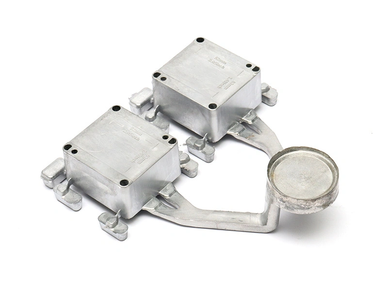
Surface Zones That Buyers Should Define Before Production
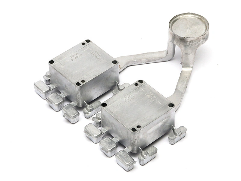
A die cast part rarely needs the same finish on every face. Buyers should mark visible cosmetic zones, hidden zones, handling edges, machined features, sealing faces, threaded areas, electrical contact points, masking areas and packaging-sensitive surfaces. This prevents two common failures: paying for unnecessary finishing on hidden areas and missing the finish requirement on the surfaces that customers actually see or assemble.
For aluminum die casting, exterior surfaces often need powder coating, painting, clear coating or anodizing alternatives depending on alloy and application. A380, ADC12 and A360 die castings are widely used for housings and structural covers, but visible finishing depends on casting surface quality and pretreatment. For zinc die castings, plating, polishing, painting and decorative coating may be more common on small hardware, lock parts, handles and consumer components.
Surface Zone | Typical Requirement | Buyer Decision |
|---|---|---|
Customer-facing exterior | Controlled texture, low visible defects, approved color or gloss | Define cosmetic zone, viewing distance and finish master |
Hidden internal wall | As-cast or lightly deburred surface | Avoid premium finishing unless corrosion or function requires it |
Threaded holes and bosses | Clean threads, controlled coating buildup, no media contamination | Specify machining, tapping, masking and gauge check |
Sealing face | Flatness, surface roughness and no coating if sealing requires metal contact | Mark CNC machining and masking requirement |
Mounting datum | Stable geometry for inspection and assembly | Separate dimensional tolerance from cosmetic finish |
Electrical contact area | Conductive or uncoated area depending on design | Define masking, plating or grounding requirement |
Packaging-sensitive finish | Protection against rub marks, chips and scratches | Confirm separators, bags, trays or individual wrapping |
As-Cast Surface Finish and Common Die Casting Marks
As-cast surface finish comes directly from die condition, alloy flow, temperature control, shot parameters, venting, cooling and ejection. Normal die casting marks can include parting lines, ejector pin marks, gate vestiges, trimmed runner areas, minor flow lines and local texture variation. These marks may be acceptable on hidden areas, but they can be unacceptable on cosmetic faces or surfaces that receive plating.
Some defects are not only cosmetic. Cold shuts may indicate poor metal flow. Heavy porosity can create coating pinholes or leakage risk. Flash and burrs can interfere with assembly. Pits and dents may remain visible after painting. A buyer should not simply ask for "smooth surface" because that phrase does not tell the supplier which defects matter and which surfaces are critical.
For zinc parts, zinc die casting can produce excellent detail and smooth surfaces, but decorative plating magnifies defects that powder coating might hide. For aluminum parts, casting texture and porosity control matter when the exterior needs coating or when machined surfaces expose internal pores.
Surface Mark or Defect | Why It Matters | Typical Buyer Control |
|---|---|---|
Parting line | Can be visible after coating or create flash cleanup work | Mark visible faces and agree on allowable line height |
Ejector mark | May be unacceptable on exterior cosmetic surfaces | Review ejector layout before tooling release |
Gate vestige | Can leave a trimmed area or texture difference | Define gate removal and finishing level |
Flow mark | May remain visible under thin paint or plating | Confirm acceptable cosmetic zone standard |
Pinhole or porosity | Can affect coating, sealing, polishing and appearance | Set defect limit by zone and function |
Burr or flash | Can affect safety, fit and coating edge quality | Specify deburring method and edge acceptance |
When Sand Blasting Improves Die Cast Surface Finish
Sand blasting, bead blasting or media blasting can unify surface texture, clean minor residue, reduce visual contrast between trimmed and as-cast areas, and prepare the surface for coating. It is useful when a buyer needs a matte texture or a better surface profile before painting or powder coating. It also helps create a consistent visual base when different areas of the casting have slightly different textures.
Sand blasting must be controlled by media, pressure, angle, distance, exposure time and masking. Aluminum oxide media can create a sharper profile. Glass bead can create a softer satin texture. Steel shot may be unsuitable for some cosmetic aluminum parts because contamination or embedded particles can create downstream corrosion or finish issues. Non-metallic media is often preferred where clean cosmetic preparation is important.
Blasting also has limits. It cannot remove deep shrinkage pits, severe cold shuts, large dents or tooling defects. Aggressive blasting may round edges, damage fine details, trap media in blind holes, change the appearance of machined areas or create adhesion variation if cleaning is poor. Threads, sealing faces, precision bores, bearing seats and electrical contact areas may need masking or post-blast cleaning.
Powder Coating, Painting and Plating Require Different Surface Preparation
Powder coating, painting and plating are not interchangeable surface finish routes. Powder coating can provide durable protection and texture, but coating thickness may affect holes, threads, tight fits and mating surfaces. Painting can support color and gloss requirements, but surface cleaning, primer selection and defect limits matter. Plating can create decorative or conductive surfaces on zinc parts, but it usually exposes pits, polishing defects and base metal problems more clearly.
For powder coating, buyers should define color, gloss, texture, target thickness, masking areas and adhesion requirements. A typical coating thickness may be roughly 60-120 micrometers for many industrial powder coating applications, but the acceptable range must match the powder system, part geometry and assembly clearance. Thick buildup around sharp corners, threaded holes and mounting slots can create assembly issues.
Painting can be selected when the product needs a controlled color, smoother visual appearance or lower coating thickness than some powder routes. Painting service for die cast parts should be validated with real castings because die casting porosity, oil residue, blasting texture and edge coverage can change the final result. Buyers should approve color and gloss with a production-representative sample, not only a flat color chip.
Machined Surfaces and Surface Finish Must Not Be Mixed Up
Machined surfaces are often part of the surface finish conversation, but they serve a different purpose from cosmetic finishing. A machined bore, sealing face, threaded hole or datum surface controls function. A cosmetic painted face controls appearance. One area may need Ra control, flatness and CMM measurement. Another may need color, texture and visual inspection. Mixing these requirements can either raise cost unnecessarily or leave functional surfaces under-controlled.
Critical machined surfaces after casting often include threaded holes, mounting holes, bearing bores, sealing faces, gasket seats, locating pads and datum surfaces. These features may need CNC machining after die casting because as-cast surfaces cannot always meet functional tolerance, roundness, perpendicularity or roughness requirements. Coating may then need masking or allowance to protect the final fit.
Buyers should identify the sequence. For example, a cast aluminum enclosure may be blasted and powder coated after machining, but threaded holes may be masked or chased after coating. A zinc decorative handle may be polished before plating, while screw holes remain controlled separately. The sequence changes cost, quality risk and inspection steps.
Inspection Standards for Die Casting Surface Finish
Surface finish inspection should define how the part will be judged, not just what the buyer hopes to see. Useful standards include visual inspection distance, lighting condition, viewing angle, cosmetic zone class, allowed defect size, allowed defect count, coating thickness, adhesion test, surface roughness for machined faces, masking accuracy, burr limit, thread cleanliness and packaging condition.
For high-visibility parts, buyers may use a finish master, a signed sample or an appearance limit sample. The sample should be made from the real die cast part, not a flat coupon. It should include the same casting alloy, surface preparation, blasting route, coating or painting process and packaging method. The finish master becomes the comparison reference for later pilot and repeat orders.
When surface defects are small or difficult to classify, stereo microscopy for surface inspection can help review pits, scratches, coating defects or local structural marks. For most production parts, the inspection plan should still translate these findings into practical acceptance limits that operators and buyers can repeat.
Inspection Item | Typical Method | Buyer Should Confirm |
|---|---|---|
Visual appearance | Defined lighting, distance and cosmetic zones | Allowed scratches, pits, stains, dents and color variation |
Coating thickness | Thickness gauge or process certificate | Target range and surfaces where thickness matters |
Adhesion | Crosshatch, pull-off or specified customer method | Test location and acceptance level |
Machined roughness | Roughness tester where functional | Ra value only on surfaces that truly need it |
Masking accuracy | Visual check, gauge check or assembly check | Threads, bores, sealing faces and grounding pads |
Thread cleanliness | Go/no-go gauge and visual cleaning check | No coating, media or burrs blocking assembly |
Packaging protection | Final outgoing inspection | No rub marks, coating chips or transport scratches |
Surface Roughness and Film Build Reference
As a quotation reference, high-pressure die cast surfaces are often reviewed around Ra 1.6-6.3 micrometers, sand-cast surfaces around Ra 6.3-25 micrometers and functional CNC-machined faces around Ra 0.8-3.2 micrometers. Powder coating commonly adds 60-120 micrometers of film, so threads, bores and close fits may need masking.
These ranges should be translated into zones and inspection methods. Buyers evaluating cosmetic and functional surfaces can use decorative coating controls for die cast parts to define appearance separately from machined fit.
ISO 21920 can define surface-texture parameters, ASTM D3359 or ISO 2409 can define coating adhesion, and ASTM B117 or ISO 9227 can define corrosion exposure. Moisture-sensitive parts should connect finish selection with anti-corrosion coating controls.
Contact or abrasion zones require separate evidence from cosmetic faces; wear-resistant coating evaluation helps prevent one visual standard from being used for every surface.
Short Case: A380 Enclosure With Blasted and Powder Coated Surfaces
A buyer needed an A380 aluminum electronics enclosure with a clean exterior, threaded bosses, a gasket face and visible front cover. The first drawing only called out "black finish." That was not enough for quoting because the supplier could not know whether the part needed blasting, powder coating, painting, masking, thread protection or a cosmetic acceptance sample.
The finish plan separated the part into zones. The exterior cover was sand blasted to create a uniform matte base before black powder coating. The gasket face was CNC machined and masked. Threaded bosses were tapped after casting and protected during coating. The drawing allowed minor internal flow marks but rejected pits, exposed metal, coating chips and scratches on the front visible face. The buyer approved a finish master from a small pilot batch before repeat production.
This approach reduced dispute risk because the inspection team was no longer judging the part from a vague color note. It also helped the buyer see the real cost drivers: blasting coverage, coating thickness control, masking labor, thread cleaning, final visual inspection and protective packaging.
What Buyers Should Include in a Die Casting Surface Finish RFQ
A surface finish RFQ should describe the finished part condition, not just the casting process. Buyers should provide 3D CAD, 2D drawing, alloy grade, visible surface zones, functional surfaces, coating or painting requirement, blasting requirement, roughness notes where functional, masking notes, allowed defects, sample approval method, quantity stage and packaging requirement. Without this information, two suppliers may quote very different finishing scopes.
For projects that combine casting and machining, post machining after casting should be reviewed together with surface treatment. The finish route may change if holes are tapped before coating, if a sealing face must remain bare metal, or if a machined surface is visible after blasting. The RFQ should make these areas clear so the supplier can plan the sequence.
RFQ Detail | Why It Matters for Surface Finish | Useful Buyer Note |
|---|---|---|
Alloy grade | A380, ADC12, A360, Zamak 3 and Zamak 5 respond differently to polishing, coating and plating | State required grade or acceptable equivalent |
Cosmetic zones | Controls where flow marks, pits and ejector marks are unacceptable | Mark A/B/C surfaces on drawing |
Blasting requirement | Changes texture, coating preparation and masking needs | Define media, texture expectation or sample reference |
Coating thickness | Affects assembly clearance, threads, slots and corrosion protection | Give target range or required coating specification |
Masking areas | Protects threads, bores, sealing faces and electrical contacts | Mark no-coating surfaces clearly |
Inspection method | Prevents disputes about appearance and acceptance | State viewing distance, finish master or test method |
Packaging | Protects the approved finish after production | Confirm separators, wrapping or tray packing for cosmetic parts |
How Surface Finish Changes Cost, Lead Time and Risk
Surface finish can change the cost and lead time of a die casting project even when the casting itself is simple. The added cost may come from blasting time, manual masking, polishing labor, coating material, curing, plating pretreatment, color matching, sample approval, inspection and protective packaging. The added lead time may come from waiting for coating samples, correcting surface defects, repeating adhesion tests or adjusting masking after the first assembled sample.
Buyers should separate cosmetic cost from functional cost. Cosmetic cost includes visible surface preparation, color matching, gloss control, polishing, defect sorting and packaging protection. Functional cost includes machining, masking, roughness control, coating thickness checks, thread cleaning and gauge inspection. Mixing these costs can make the quote hard to compare because one supplier may include finished-part inspection while another may quote only raw casting plus basic coating.
Surface finish risk also changes by production stage. A prototype may be hand finished to show the target appearance, but that does not prove the same result can be repeated in mass production. A pilot batch should verify whether blasting coverage, coating thickness, masking and inspection can be repeated across multiple parts. For repeat orders, the supplier should keep the same finish master, process route and inspection standard so appearance does not drift between batches.
Cost or Lead Time Driver | Why It Changes the Project | How Buyers Can Control It |
|---|---|---|
Manual masking | Protects threads, sealing faces and contacts but adds labor | Mark only the surfaces that truly need protection |
High cosmetic sorting | Strict visible surface limits increase rejection and inspection time | Use A/B/C surface zones instead of one strict rule everywhere |
Color or gloss matching | May require sample rounds and supplier approval | Provide a physical reference or approved finish master |
Coating thickness control | Affects assembly clearance and protection | Define target range and no-coating areas on the drawing |
Post-finish thread cleaning | Needed when coating or media enters holes | Confirm masking or chasing strategy before production |
Protective packaging | Prevents scratches after the part already passed inspection | Use trays, separators or wrapping for customer-facing finishes |
How Neway Connects Casting, Finishing and Inspection
Neway can review die casting surface finish from the first drawing stage by checking part geometry, alloy direction, tooling mark locations, machining areas, blasting needs, coating route, masking, inspection and packing. This matters because a finished surface is created by the full production chain, not by a single final operation.
For buyer teams comparing surface options, premium surface finishing for die cast components can be considered together with service-level routes such as sand blasting, powder coating, painting, CNC machining and inspection. The best route is the one that protects the part function and appearance at the required production quantity.
Before releasing pilot or mass production, buyers should confirm the finish sample, defect limits, masking method, coating thickness, thread condition, machined surfaces, inspection records and packaging. A clear surface finish standard gives both buyer and supplier the same target for repeat orders.
FAQ