What Is Arc Anodizing? Process, Properties, and Industrial Applications
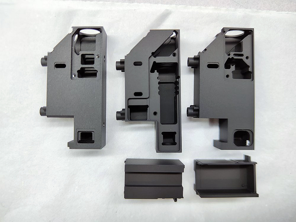
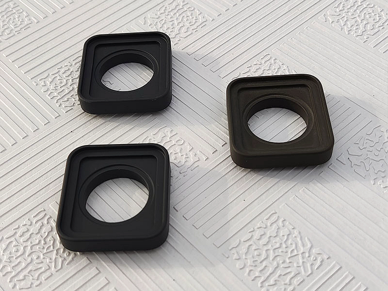
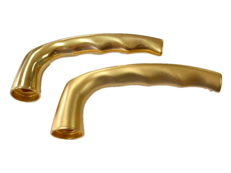
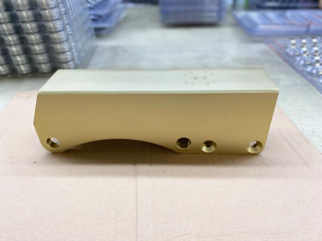
Arc anodizing is the project term used here for micro-arc oxidation (MAO), also called plasma electrolytic oxidation (PEO). It is an electrochemical conversion process for selected light-metal alloys. A controlled electrical waveform drives the growing oxide into dielectric breakdown, producing many short-lived surface discharges. Those events change how the oxide forms and allow a ceramic-like coating architecture to develop from the substrate and electrolyte. The result can support wear, corrosion, electrical, thermal-surface or bonding requirements, but only after the exact alloy, geometry, process route and final coating stack have been qualified.
That definition matters because arc anodizing is not simply a thicker version of conventional anodizing. It uses different electrical conditions, has different surface morphology, and often needs a different post-treatment and inspection plan. Nor does MAO inherently create a hard, sealed or defect-free surface. The useful property comes from the complete system: substrate condition, discharge regime, oxide architecture, finishing operation and service environment.
What Happens During Arc Anodizing?
The workpiece acts as an electrode while immersed in a formulated aqueous electrolyte. Early in the cycle, an oxide grows by electrochemical reactions much as it does in anodizing. As the applied waveform and surface resistance evolve, localized dielectric breakdown begins. The visible micro-discharges are distributed reaction sites, not an uncontrolled welding arc. Their location, intensity and duration change throughout the run.
At each active site, oxide is formed, transformed, dissolved and redeposited over very short distances. Constituents from the electrolyte may enter the coating as well. The resulting layer can contain multiple phases and usually has a gradient rather than one uniform composition. A comparatively compact region may exist nearer the metal, while the outer region may be rougher and contain discharge channels or open pores. The exact architecture is route-specific; cross-section microscopy is a better basis for a claim than a generic MAO diagram.
Power-supply mode, waveform, current response, electrolyte chemistry, bath temperature, agitation, fixture contact and treatment time all influence discharge behavior. These variables interact. Increasing one setting does not translate directly into more useful thickness or better performance. Aggressive discharges can raise roughness, enlarge defects, concentrate heating or damage edges. Process development therefore aims for a repeatable electrical response and coating architecture, not the brightest visible sparks.
Industrial Arc Anodizing Workflow
1. Define the Engineering Job
A sound route starts with the failure mode. "High-performance coating" is not an acceptance criterion. The drawing and purchasing specification should state whether the surface must resist sliding abrasion, particle erosion, a particular corrosive medium, an electrical potential, heat exposure, adhesive debonding or a combination. Contact pressure, counterface, lubricant, temperature cycle, cleaning chemistry and allowable dimensional change are part of that definition.
This is also the point to compare MAO with alternatives. Conventional anodizing may be more appropriate for dyeable color, a smoother surface or a less demanding exposure. Paint, powder, plating, conversion coating or a duplex MAO-plus-sealer system may better address another failure mode. A process name should follow the requirement, not replace it.
2. Verify the Substrate and Part Condition
Aluminum, magnesium and titanium alloy families are the usual candidates, but the metal name alone is insufficient. Alloying phases, product form, heat treatment, porosity, inclusions and segregated cast surfaces can change discharge distribution and local coating growth. The same nominal alloy can respond differently on an as-cast face and a machined face. The screening principles in the arc-anodizing substrate guide should be applied before cosmetic or functional limits are frozen.
For an aluminum die casting, trapped gas, cold laps, exposed pores and silicon-rich areas can become visible after cleaning or treatment. MAO does not repair those discontinuities. Production-intent castings, rather than a wrought coupon, should be used to establish the route when casting surfaces remain exposed.
3. Prepare, Mask and Fixture
Oil, polishing compound, machining coolant and shop soil must be removed without attacking the alloy or creating an uncontrolled surface. Pretreatment is selected for the alloy and final requirement. Heavy abrasive preparation may improve mechanical keying for one stack but make a cosmetic surface too rough for another. The approved sequence should identify cleaner, rinse control, any etch or activation, and the permitted time before treatment.
Electrical contact points need enough area and pressure to carry the programmed load. They also leave an untreated or disturbed witness area, so their location belongs on the drawing or fixture plan. Threads, bearing seats, sealing lands, ground paths and close fits may need masking. Masking must survive the electrolyte and electrical cycle. Its edges should be included in approval because current concentration and undercutting can make the transition zone different from an open flat surface.
4. Run and Monitor the Electrical Cycle
Parts are loaded with controlled spacing and orientation, then processed under an approved recipe. Useful run records may include waveform identification, voltage and current response, energy or charge indicators, bath chemistry checks, temperature history, time, load configuration and alarms. Which variables are controlled depends on the equipment and the qualified window.
Geometry affects the electrical field and fluid movement. Sharp edges, deep recesses, blind features and tightly nested parts may not behave like an accessible flat coupon. Fixtures can shadow solution flow or alter current distribution. A representative load study is therefore part of scale-up. The broad MAO route and standards overview can organize specifications, but the production recipe still needs part-specific evidence.
5. Rinse, Finish and Release
After treatment, parts are rinsed and dried under conditions that avoid residue or staining. The as-formed outer surface may then be left intact, smoothed, sealed, impregnated, painted or combined with another functional layer. Post-treatment is not an afterthought: it can dominate corrosion pathways, friction, dielectric leakage, cleanability and appearance. Removing the rough outer peaks can improve dimensional or sliding behavior while also changing coating thickness and exposing a different architecture.
The approved final stack must be inspected after all finishing, not only after the MAO cycle. Relevant post-processing operations and any later CNC machining should be sequenced deliberately. Machining through a qualified coating can expose substrate and create an unprotected edge; machining first can leave features whose coating buildup affects fit.
How to Interpret MAO Coating Properties
MAO is valuable when its architecture is matched to a measurable function. A data-sheet adjective is not enough. Hardness, for example, does not by itself predict wear because counterface material, load, debris, roughness, lubrication, coating support and test method all matter. Corrosion behavior depends on connected porosity, sealing, edge condition, substrate defects and the exposure chemistry. Electrical behavior depends on the weakest local path, not just an average oxide thickness.
| Design objective | What MAO may contribute | Main conditions and risks | Evidence to request |
|---|---|---|---|
| Abrasion or sliding wear | Hard oxide phases and a load-bearing conversion layer | Outer roughness, brittle cracking, weak substrate support, counterface wear and lubricant compatibility | Application-relevant wear test, profilometry, cross-section and inspection of both mating surfaces |
| Corrosion control | A barrier architecture and a base for sealing or a duplex topcoat | Open paths, cast porosity, cut edges, masking transitions, galvanic contact and damage in service | Exposure on production alloy and final stack, with defined failure criteria and post-test sectioning |
| Electrical insulation | A metal-integral oxide with useful dielectric behavior | Thin regions, pores, sharp edges, humidity, contamination, thermal cycling and breakdown damage | Voltage test using the real electrode geometry, environmental conditioning and leakage or breakdown criteria |
| Thermal-surface function | Modified emissivity or a ceramic thermal interface for a defined design | Coating is not automatically a heat-spreading improvement; contact resistance and layer thickness may oppose heat flow | Assembly-level thermal test under intended mounting, power and airflow conditions |
| Bonding or topcoat adhesion | A textured oxide surface that can anchor a compatible secondary layer | Residue, weak outer material, excess roughness, moisture and primer incompatibility | Approved preparation, adhesion test after conditioning and failure-mode examination |
| Cosmetic or tactile surface | A natural matte or micro-textured appearance, sometimes modified by finishing | Alloy variation, discharge distribution, roughness, gloss and lot-to-lot color drift | Production-intent limit samples, instrument readings where useful, and controlled viewing conditions |
Coating thickness remains a useful process and drawing variable, but it must be defined by measurement location and method. MAO surfaces are textured, and the architecture can grow both above and into the original surface reference. A single average thickness does not describe a thread, bore, edge or sealing land. Dimensional planning should identify which surfaces are coated, masked or finished after treatment and how final size will be verified.
Substrates and Alloy Response
Aluminum alloys are widely processed, including wrought, cast and additively manufactured forms, but each route needs its own qualification. Silicon-, copper- or intermetallic-rich regions can affect local reactions. That does not make a high-silicon casting automatically unsuitable, nor does it make one lower-silicon die-casting grade universally preferable. It means surface uniformity, architecture and function must be demonstrated on the selected alloy and manufacturing route.
Magnesium alloys can form MAO conversion layers, often as part of a corrosion-control stack. Their reactive substrate makes defects, cut edges and post-treatment especially important. Titanium alloys can also be treated, with outcomes tailored toward wear, surface chemistry, texture or optical response. A titanium MAO surface is not automatically approved for implantation or patient contact; those uses require separate biological, cleaning and regulatory evidence.
Zinc and copper alloys are not routine substitutions in a recipe developed for aluminum, magnesium or titanium. Any unusual-substrate proposal needs processor-specific proof of stable treatment, coating identity, adhesion, safety and function. Often another finish is the more direct route. The substrate question should be closed before tooling, masking and inspection costs are committed.
Where Arc Anodizing Is Used
Industrial uses are selected by component-level exposure, not by industry label. A sliding aluminum guide may need controlled friction and wear evidence. A magnesium electronics enclosure may need a sealed corrosion stack with grounded areas masked. A power-conversion housing may use selected coated regions for dielectric separation, but the assembly still requires creepage, clearance, humidity and breakdown evaluation. A pump or fluid-control component may value erosion or corrosion behavior only if the test medium and flow reproduce service.
Aerospace and transportation programs may consider MAO where mass reduction puts an aluminum, magnesium or titanium surface into wear, heat or corrosion exposure. Industrial equipment may use it on rollers, housings, guides or fixtures. Electronics programs may use texture, insulation or a bonding base. In every case, the coating must be assessed within the component drawing, assembly contacts and maintenance environment. An industry example is a screening clue, not evidence that the process is approved for a particular part.
The broader benefits of arc anodizing are most credible when expressed as prevented failure modes. If the coating does not remove a known risk, enable a required material choice or simplify a qualified stack, its added processing burden may not create buyer value.
Limitations and Common Specification Errors
Treating MAO as pore-free: discharge channels and outer porosity can be part of the architecture. Corrosion or dielectric designs may require sealing, smoothing or a duplex layer.
Specifying hardness alone: a hard constituent cannot compensate for poor support, cracks, damaging roughness or the wrong counterface.
Ignoring geometry: edges, recesses, small bores, contact points and masking boundaries may control the real failure.
Approving a coupon instead of the part: coupons help monitor a process, but they do not reproduce cast defects, current distribution or finishing access on a complex component.
Assuming the natural finish is a controlled color: visual outcome can shift with alloy lot, surface preparation, load and recipe. Cosmetic programs need boundary samples and viewing rules.
Comparing coating prices without final stacks: MAO, sealed MAO, polished MAO and MAO plus an organic topcoat are different purchased conditions. The arc-anodizing cost guide is useful only when scope is held constant.
Qualification and Production Control
A practical qualification plan links every important requirement to a specimen, method and acceptance rule. Start with production-intent parts from the chosen alloy route. Establish cleaning, contact, masking, load arrangement, MAO recipe and final finishing. Measure dimensions and surface condition before and after treatment. Section representative locations to examine architecture, especially at the features most likely to be thin, rough or damaged.
Functional testing should reproduce the governing exposure as closely as the program can justify. Wear tests need the specified counterface, motion, load and lubricant. Corrosion tests need the final sealed or topcoated stack, relevant damage state and a defined failure threshold. Electrical tests need actual electrode geometry and conditioning. Cosmetic assessment needs agreed masters, lighting, viewing distance and allowed variation. When a standard method is used, cite its revision, specimen preparation and pass criterion rather than writing only "tested to standard."
Production control then monitors variables shown to predict those outcomes. A processor may track bath condition, electrical signatures, temperature, fixture condition, load pattern, rinse quality, visual state, thickness at designated locations and periodic functional coupons. The control plan should state reaction rules for drift and changes. A new alloy source, heat treatment, casting route, pretreatment chemical, fixture, recipe or sealer can invalidate the original relationship and may require partial or full requalification.
What to Include in an Arc Anodizing RFQ
Send enough information for the processor to assess both feasibility and inspection. At minimum, the RFQ package should include:
part drawing, revision, 3D data when useful, annual and order quantities, and the current manufacturing route;
exact alloy designation, material condition, product form, casting or additive route, and any approved material-source limits;
surfaces to coat, mask, contact, smooth or machine afterward, with threads, bores, sealing lands and electrical grounds identified;
service environment, failure mode, mating material, motion, load, fluid, voltage, temperature and cleaning exposure relevant to the coating;
final coating stack, including sealing, impregnation, polishing, paint, lubricant or adhesive, plus any prohibited substances;
dimensional limits in the final coated condition and the measurement method for textured surfaces;
functional tests, standard revisions, specimen locations, sample frequency and numerical or visual acceptance criteria;
cosmetic zones, color or gloss controls, limit samples and viewing conditions where appearance matters;
traceability, records, change-notification and qualification deliverables required by the purchasing organization.
A capable supplier should respond with open technical questions, the proposed process boundary and a trial plan where uncertainty remains. The buyer should expect qualification effort for a new alloy, geometry or function. Any promise of fixed performance without reviewing those inputs is weaker than a conditional proposal tied to measurements.
Engineering Decision
Arc anodizing is a useful MAO/PEO conversion route when a selected light-metal part needs a ceramic-like surface architecture and the requirement can be proven on the final system. Choose it after defining the failure mode, screening the exact substrate and comparing realistic alternatives. Approve the coating only after the production-intent alloy, geometry, masking, post-treatment and test method agree with the drawing. Capability should also be repeated across the agreed production load and material range, because a successful development part does not establish lot behavior. That approach turns "arc anodized" from a process label into an inspectable engineering requirement.
FAQs