Arc Anodizing Classifications: Standards, Types, and Industrial Applications
Arc anodizing is best classified as a plasma-assisted electrolytic oxidation process family, commonly called micro-arc oxidation (MAO) or plasma electrolytic oxidation (PEO). It is not automatically MIL Type III sulfuric hard anodizing, and MAO and PEO are not reliably separated by one universal technical boundary. For an industrial component, classify the requested coating by substrate, electrical waveform, electrolyte-derived chemistry, coating architecture, post-treatment and verified performance. The purchase specification must define those items because the label alone does not.
Resolve the process name before discussing a standard
"Arc anodizing" is used inconsistently across supplier literature. In this article it means an electrolytic oxidation route in which dielectric breakdown and localized discharges contribute to oxide formation on a suitable valve metal. MAO and PEO are often used for overlapping versions of that route. A supplier may prefer one term based on region, equipment history or branding rather than a measurable change in coating physics.
Conventional anodizing and Type III hardcoat also form oxide electrochemically, but they use a different processing regime and specification tradition. A Type III callout should not be fulfilled with PEO unless the drawing and customer authorize that substitution. Conversely, citing a conventional hard-anodize specification does not fully define a discharge-formed ceramic coating. Procurement should require the processor to state the process family and governing document in the quotation.
Why classifications are project-specific
There is no single global Type I/II/III ladder that classifies every MAO or PEO coating. Research papers and commercial systems may group coatings by current mode, voltage control, discharge behavior, electrolyte family, thickness, phase composition or intended property. Those classifications can describe the process, but they are not interchangeable acceptance classes. Two coatings described as "PEO" may differ substantially in roughness, connected porosity, phase content and response to sealing.
A usable industrial classification has two layers. The process definition controls what is made: substrate condition, electrical control, electrolyte, time endpoint and post-treatment. The performance definition controls what is accepted: geometry, thickness distribution, wear response, corrosion behavior, dielectric performance, surface roughness or other relevant characteristics. Both belong in the technical agreement.
Classify first by substrate and starting surface
PEO-type processes are associated with valve metals that can support a dielectric oxide under suitable electrochemical conditions. Aluminum, magnesium and titanium are common examples, but the applicable alloy and route must be qualified. The fact that a metal family is generally treatable does not prove that a specific casting alloy, heat treatment or mixed-material assembly will produce the required layer.
For aluminum die castings, silicon-rich phases, copper- or iron-bearing intermetallics, pores, laps and as-cast skin variation can alter discharge distribution and coating structure. The specific response of an AlSi10Mg casting must be qualified rather than inferred from a wrought coupon. A machined face may also respond differently from an as-cast face on the same part. Wrought, additively manufactured and cast substrates should therefore be separate qualification populations unless evidence supports transfer.
Classify the electrical regime without prescribing an unsupported recipe
Power delivery may be described as direct, pulsed unipolar, bipolar or another controlled waveform. Relevant variables can include current or voltage control, pulse timing, polarity balance, ramp strategy and endpoint. These variables influence when discharges begin, how energy is distributed and how the layer evolves. They do not independently predict performance; electrolyte, substrate, bath condition, fixture and geometry interact with them.
The customer usually needs a qualified result, not the processor's proprietary settings. Unless the process is customer-owned, a drawing can require an approved process identifier and performance limits while the detailed waveform remains in controlled supplier documentation. Any parameter window stated in a quote must be traceable to the selected alloy and geometry. Copying a voltage or current density from another coating system is not a process qualification.
Electrolyte contribution creates different ceramic systems
The coating can contain oxide derived from the substrate plus species incorporated from the electrolyte. Electrolyte family, additives and bath condition can affect phase formation, discharge behavior, porosity and subsequent sealing or impregnation. A "ceramic oxide" description is therefore incomplete. Where composition matters for electrical, wear, thermal, biomedical or chemical compatibility, specify the relevant analytical evidence and allowable substances.
Do not infer food, medical, aerospace or environmental acceptability from a ceramic appearance. Those uses may require separate material declarations, extractables review, cleanliness, biocompatibility, restricted-substance evidence or customer process approval. The coating processor and relevant laboratory must confirm the current scope; a general arc anodizing service page is not certification.
Coating architecture is more useful than "hard" or "decorative"
A discharge-formed coating can contain an inner region near the metal, a denser functional region and a rougher or more porous outer region. The exact architecture varies with substrate and process. Surface-connected pores, discharge channels, local cracks and rough nodules may be natural features, but their amount and effect must be assessed against the intended function. A polished cross-section represents one location, not automatic continuity across a complex component.
Terms such as hard, dense, smooth, decorative or high-temperature are marketing shorthand unless linked to methods and limits. A coating optimized for low wear may need a ground or polished outer surface. A dielectric coating may prioritize breakdown behavior and defect control. A bond-coat application may deliberately retain topography. A corrosion system may rely on impregnation or a topcoat to close connected paths. Classification should state which architecture is required and how it is verified.
Post-treatment creates a coating system, not a single layer
PEO or MAO can be followed by sealing, impregnation, polishing, grinding, painting or another compatible topcoat. Post-treatment may reduce connected porosity, change roughness, improve stain resistance, prepare a bearing surface or supply a color unavailable from the ceramic layer alone. It can also alter dimensions, electrical behavior, friction and inspection access.
The RFQ should separate the as-formed oxide requirement from the final system requirement. If the topcoat supplies most corrosion protection, a salt-spray result cannot be attributed to PEO alone. If polishing removes the porous outer region, thickness before and after polishing may serve different purposes. State the final operation sequence and test the same sequence that production parts receive.
A practical classification matrix
| Classification axis | Examples of controlled choices | Why it matters | Evidence |
|---|---|---|---|
| Substrate | Alloy, product form, heat treatment, as-cast or machined condition | Controls discharge response, defects and achievable architecture | Material record, surface route and production-intent samples |
| Electrical regime | Controlled waveform family and approved process identifier | Influences energy delivery and layer evolution | Processor qualification and controlled run records |
| Electrolyte/coating chemistry | Approved bath family and relevant incorporated species | Affects phases, porosity and compatibility | Process declaration and selected chemical/phase analysis |
| Architecture | Functional thickness, roughness, connected defects and local continuity | Links the process to wear, dielectric or barrier behavior | Calibrated thickness method, cross-sections and surface inspection |
| Post-treatment | As-formed, sealed, impregnated, polished or topcoated | Can dominate final dimensions and protection | Operation sequence and final-system tests |
| Performance class | Wear, corrosion, dielectric, thermal or bonding requirement | Prevents one property from standing in for another | Project-specific test method, specimen and acceptance limit |
Standards should be selected by function
A standard may define a test method without defining a suitable coating. Another may cover conventional anodic coatings but not the specific PEO system. A customer specification may combine process definition, qualification and acceptance in one document. The engineering team should create a requirements matrix showing what each cited document actually governs: substrate, coating process, thickness measurement, wear test, corrosion exposure, electrical test, adhesion assessment, sampling or reporting.
Do not cite military, aerospace, automotive or medical language as a proxy for severity. Confirm the current document revision, scope and contractual precedence. When no single standard covers the required PEO system, use a controlled customer or supplier specification supported by recognized test methods. Qualification should establish that those methods are meaningful for a porous ceramic layer on the actual geometry.
How to specify wear-focused arc anodizing
A wear classification must name the contact system. Counterface material and finish, load, motion, speed, lubrication, debris, temperature and permitted failure all influence the outcome. Coating microhardness can help characterize a region, but it does not predict component wear by itself. Surface roughness and loose asperities may damage the mating part even when the ceramic phase is hard.
Use representative wear specimens or finished components where possible. Record whether the outer layer is polished and whether a seal or lubricant is present. Measure both coating and counterface damage. If the part operates under rolling contact, impact or fretting rather than sliding abrasion, select a method that represents that mechanism rather than defaulting to a familiar abrasion test.
How to specify corrosion-focused systems
Corrosion performance depends on substrate chemistry, casting integrity, connected coating defects, edge condition, rack contacts, post-treatment and the exposure itself. Increasing nominal thickness does not necessarily close discharge channels. A sealed or topcoated system may outperform the as-formed oxide, but it must be identified as that complete system.
Neutral salt spray can be one comparison method, not a service-life clock. Cyclic corrosion, immersion, humidity, chemical splash or galvanic-couple testing may better represent some products. Define specimen preparation, scribe or unscribed condition, exposed edges, duration, inspection intervals and failure rating. A coupon can monitor the process; the component demonstrates behavior at casting pores, corners and machined transitions.
How to specify electrical and thermal functions
For electrical isolation, define working voltage, test voltage, electrode geometry, contact area, ramp, environment, leakage limit and breakdown criterion. Coating thickness alone cannot prove insulation because local pores, edges, fixtures and assembly damage create weak points. Test at locations linked to the circuit risk and distinguish dielectric withstand from long-term insulation resistance.
Thermal claims need similar discipline. A ceramic layer may change emissivity, interface resistance, heat spreading or thermal-barrier behavior depending on thickness, composition, roughness and contact. "Heat resistant" does not say whether the objective is to protect the substrate, radiate heat, limit conduction or survive thermal cycling. Use a component-level thermal test with the intended assembly when temperature management drives selection.
Industrial applications follow failure modes
Wear and sliding interfaces
Guides, sleeves, pump or actuator features may use PEO-type coatings where a ceramic surface and qualified counterface reduce wear. The design still needs edge support, finishing and lubrication decisions. Coating a poorly supported thin edge can create a brittle failure site rather than a durable interface.
Electrical housings and isolation features
Power-electronics parts may need localized insulation while preserving grounding pads and thermal contacts. Masking, racking and post-machining become part of the electrical design. Qualification should include the finished geometry and assembly loads, not only a flat coated panel.
Corrosive or chemically exposed hardware
Light-metal housings and brackets can use a sealed or topcoated PEO system when the chosen exposure and defect criteria are met. Drainage, crevices, fastener couples and handling damage may control field behavior. Finish selection cannot compensate for an unresolved galvanic or water-trap design.
Bonding and topcoat foundations
A controlled porous surface can be useful beneath a sealant or topcoat. In this case, adhesion, contamination, open time and coating-system compatibility matter more than a maximum ceramic hardness. Validate the complete stack and the production delay between operations.
Integrate classification with die casting and machining
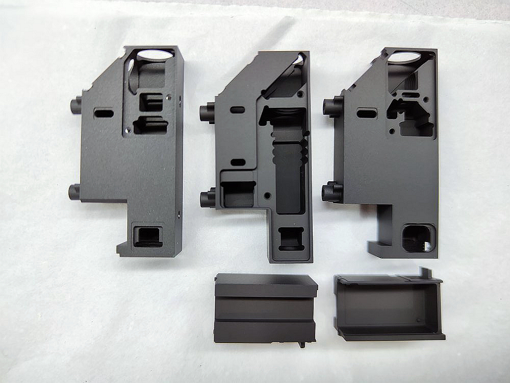
The finish decision belongs before tooling release. Gate and overflow placement, venting, local wall thickness and process stability affect the surface presented to PEO. Machining removes the die-cast skin and can expose pores. The drawing should identify which faces are as-cast, machined, masked, polished after coating or intentionally bare. For more on the substrate issue, review the anodizing limits of aluminum die castings without assuming conventional and plasma-assisted oxide routes behave identically.
Most precision machining is easier before the ceramic layer is formed. Post-coating grinding or lapping may be planned for a wear face, but ordinary cutting through the coating exposes metal and changes the protective system. CNC machining, masking and final coating allowance should therefore be quoted as one route. Pre/post dimensions must use agreed datums and methods.
Qualification and production control
Begin with production-intent parts from the selected alloy, casting or machining route and surface preparation. Map coating thickness or another architecture measure at high- and low-risk locations. Section representative areas when destructive analysis is needed. Run the functional tests tied to the requirements matrix. Approve post-treatment and final dimensions at the same time.
Production records should connect substrate lot, casting cavity or manufacturing batch, prefinish operation, PEO load, approved process identifier and post-treatment. Monitor characteristics that predict the identified failure, not every available laboratory metric. Changes in alloy source, heat treatment, tool condition, machining route, cleaning, electrolyte system, waveform family, fixture or topcoat need a defined notification and requalification decision.
Create a coating code that survives quotation
A project coating code should point to a controlled requirement rather than compress the recipe into the drawing. One workable structure records substrate/product form, approved MAO/PEO process identifier, final post-treatment state and performance class. The drawing can then use the code on each surface while the referenced specification defines tests, sampling, rack and mask rules, dimensional condition, reports and change control. Avoid codes such as "PEO hard black" that mix an acronym, subjective property and color without acceptance evidence.
When bids return, normalize each one against that code. Confirm whether thickness refers to the total layer or a functional region, whether polishing occurs before measurement, whether corrosion testing covers bare PEO or the final seal/topcoat, and whether dielectric values apply to coupons or finished parts. Record exclusions for deep holes, internal passages, rack points, alloy families and part size. A quotation is technically equivalent only when its process sequence and evidence satisfy the same rows; a similar coating name is not enough.
RFQ inputs for an arc anodizing project
Provide the exact substrate specification and product form; casting or machining route; controlled drawing and 3D model; annual and lot quantity; service environment; failure mode; required coating system; surfaces to coat, mask, rack, polish or leave bare; finished dimensions; mating materials; wear, corrosion, dielectric, thermal or bonding tests; specimen and sampling rules; documentation; packaging; and change-control expectations. State whether "arc anodizing" means MAO/PEO in the project vocabulary.
Ask the supplier to identify the qualified process family, current substrate range, outsourced operations and laboratory scope. Request a trial plan when architecture or performance has not been demonstrated on the actual alloy and geometry. Compare quotations by included process, post-treatment, inspection and rejection responsibility, not by coating name or unit price alone. The related guide to substrates suitable for arc anodizing can support screening, but production approval remains tied to the exact material and part.
Classification decision
The defensible classification of arc anodizing is not a list of decorative and hard Types. It is a controlled description of substrate, discharge process, electrolyte contribution, coating architecture, post-treatment and verified function. MAO and PEO can describe the same broad family unless a project specification gives them distinct definitions. Type III hard anodizing remains a separate callout unless an authorized document states otherwise.
For buyers, the useful outcome is a coating code that points to an approved process and an acceptance matrix. For designers, it is a surface system connected to fits, contact pairs, electrical paths and environment. For suppliers, it is a reproducible route with defined change triggers. That structure supports industrial use without inventing a universal hardness, thickness or service-life class.
Related arc anodizing questions