English

How does arc anodizing integrate with die casting and CNC workflows?

Table of Contents
Begin the finish review before die tooling release
Control the cast surface delivered to machining
Machining creates several distinct surface populations
Select the manufacturing sequence by surface function
Racking and masking are design inputs
Post-treatment and machining cleanliness must align
Use one control plan across supplier boundaries
RFQ package for the integrated route

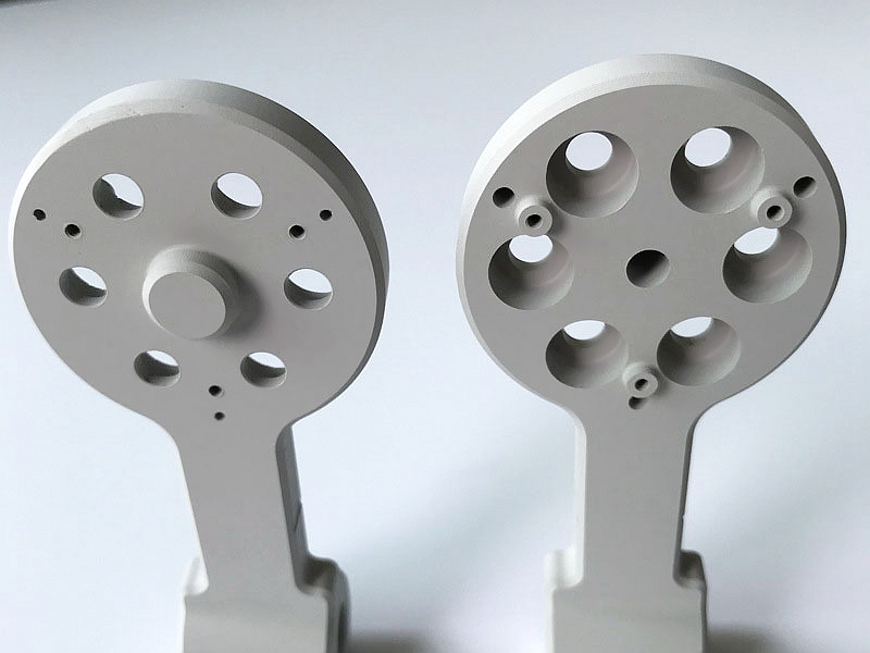
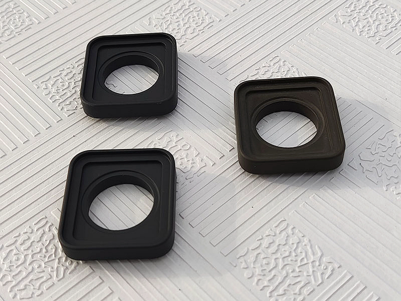
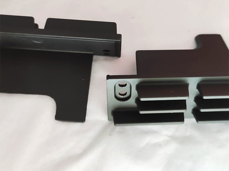
Arc anodizing integrates with die casting and CNC machining by treating the substrate surface, machining sequence, masking, coating allowance, post-treatment and final inspection as one controlled route. Most conventional cutting is completed before MAO/PEO because the ceramic layer is abrasive and cutting through it exposes aluminum. However, planned post-coating grinding, lapping or local removal can be valid. The drawing must identify each as-cast, machined, coated, masked, polished and bare surface and define the finished condition.

Begin the finish review before die tooling release

Gate, overflow, vent, ejector and parting-line locations affect surfaces later exposed to plasma electrolytic oxidation. Flow boundaries, laps and near-surface porosity can change discharge behavior or become visible after cleaning. Place high-risk process witnesses away from functional coating zones where tooling and fill permit. Mark zones that require wear, dielectric, corrosion, bonding or appearance performance.

Alloy selection must balance casting and coating needs. A360 is not automatically the best PEO substrate, and it should not be selected on an unsupported silicon comparison. A380, ADC12, AlSi10Mg or another alloy may be viable after project qualification. Review fluidity, leakage, strength, thermal behavior, tool life, supply and coating evidence together.

Control the cast surface delivered to machining

Die-casting process stability affects the skin on which coating may form. Identify release-agent control, trimming, blasting, cleaning and storage where they affect the finish. Tool wear or vent blockage can create new surface defects even if dimensions remain acceptable. Cosmetic inspection alone may miss subsurface pores that machining exposes.

Trace representative parts to cavity, alloy lot and casting batch during qualification. Section high-risk regions when architecture matters. If the finish provider receives parts from multiple casting sources, do not assume one PEO recipe transfers without review. Substrate variation is part of the coating process input.

Machining creates several distinct surface populations

CNC machining removes the cast skin, changes roughness and can reveal pores or intermetallic distributions. An as-cast wall, machined bore and blended edge may develop different coating architecture on one part. Include every important surface population in trial measurements and functional tests. Machining coolant, deburring media and cleaning residues also require control before coating.

Finish dimensions must account for the qualified coating and any post-coating polishing. Do not apply a generic growth factor. Mark whether a dimension is inspected before coating, after PEO or after final finishing. Threads, tight bores, gasket lands, bearing seats, grounding pads and bond areas need an explicit coat/mask/finish decision.

Select the manufacturing sequence by surface function

SequenceUseful whenMain riskControl
Cast, machine, PEO, final inspectCoating should cover machined features and no final material removal is neededDimensional build and roughness alter fitsQualified allowance, masking and post-coat measurement
Cast, machine, PEO, polish/lapA wear face needs a controlled final topographyToo much removal exposes porous region or substrateStock allowance, removal limit and architecture verification
Cast, PEO, local grind/machineA deliberately bare or precision area is required afterwardChipped edge and loss of local protectionDrawing-defined boundary, tool route and exposed-metal disposition
Cast, rough machine, PEO, finish grindFinal geometry depends on a grindable coating systemVariable coating stock and expensive rejectionProcessor/machinist capability trial and mapped allowance
Cast, machine, mask, PEO, topcoatDifferent surfaces need ceramic, bare metal and barrier finishMask transitions, adhesion compatibility and stack dimensionsComplete route qualification and interface inspection

Racking and masking are design inputs

The PEO process needs electrical contact and fixture support. Rack marks are local coating interruptions and may affect appearance, corrosion or electrical function. Define permitted locations with the processor. Heavy or asymmetric parts need secure fixturing; complex geometry may experience different current distribution and gas release. A blanket statement that PEO coats every surface uniformly is not credible.

Masking methods must tolerate the qualified process and geometry. Deep holes, trapped volumes and narrow gaps need drainage and cleaning review. If a bare pad is required for grounding, define its final area and corrosion boundary. If a threaded hole is masked, identify the gauge condition after all processing. These decisions belong on the controlled drawing or referenced finish map.

Post-treatment and machining cleanliness must align

Sealing, impregnation, polishing or topcoating can change dimensions and compatibility with coolants, adhesives or gaskets. The process sequence should prevent trapped contamination. Parts that return to machining after coating require chip and fluid removal that does not attack or stain the remaining system. Packaging should protect brittle edges and polished wear faces.

When a coating defect is found after machining or PEO, establish whether repair is authorized. Stripping may consume substrate and expose casting porosity. Local recoating may not restore continuity. A recurring repair indicates that the sequence, tolerance or process control needs correction; it should not become an undocumented standard route.

Use one control plan across supplier boundaries

Casting, machining and coating may occur at different organizations. Assign ownership for substrate acceptance, prefinish cleaning, coating qualification, post-treatment, dimensional release, functional tests and nonconformance decisions. Transfer records should include part revision, material/casting lot, machining status, protected surfaces and cleanliness requirements. Confirm current capabilities and outsourced operations in the quotation rather than assuming an integrated service.

First-article approval should include pre/post dimensions, coating maps, selected cross-sections, functional tests and final appearance where relevant. Production traceability should connect those outcomes to the coating process identifier. Changes in tool condition, alloy source, machining program, coolant, cleaning, fixture, PEO route or post-treatment need a documented review.

RFQ package for the integrated route

Provide the model and drawing, alloy specification, casting process, expected volume, surface-state map, machining stock, final datums and tolerances, PEO requirement, masked/rack areas, post-treatment, contact or assembly details, service environment, tests, sampling, packaging and change control. Ask casting, machining and coating suppliers to return one sequence map with responsibilities and open feasibility points.

A successful integration is not simply die cast, machine and coat. It is a route in which each operation creates the correct input for the next and the final evidence releases the actual component. For related substrate limits, compare the broader guidance on whether aluminum die castings can be anodized, while keeping conventional anodizing and MAO/PEO requirements distinct.

Copyright © 2026 Diecast Precision Works Ltd.All Rights Reserved.