CNC Fixture Design for Machined Castings: Datum, Support and Clamp-Control Decisions
CNC fixture design for machined castings must locate a part from surfaces that contain normal draft, texture, parting-line variation and local distortion, then hold it against cutting forces without bending the geometry being machined. Machine positioning accuracy cannot correct a part that rocks on uncontrolled cast skin, shifts against chips or springs back after clamp release.
The fixture should constrain the required six degrees of freedom with the fewest reliable contacts, support cutting reactions close to the load path and preserve access for tools, chips and inspection. It must also accept the approved variation from multiple casting cavities or lots. A nest that fits one selected sample tightly can reject or distort normal production.
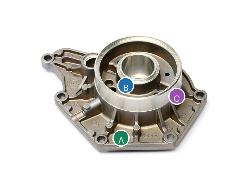
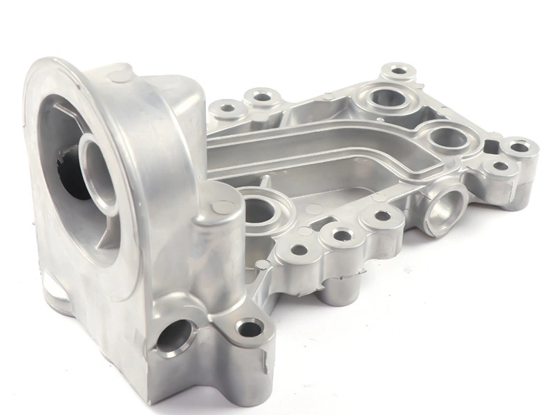
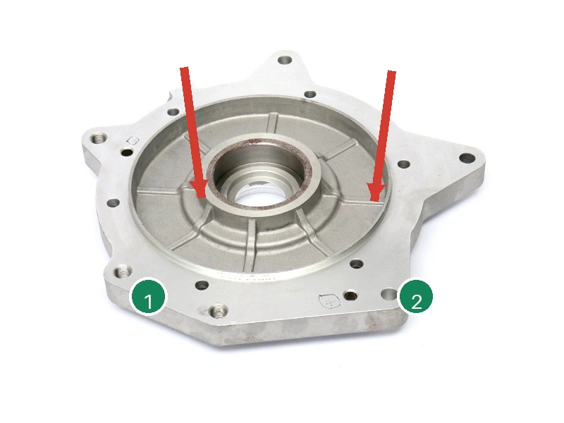
The images show a complex cast housing from two views. They support discussion of possible locating pads, openings and clamp-access limits, but they do not show the actual fixture or prove any machining result.
Why a Casting Fixture Differs From a Billet Fixture
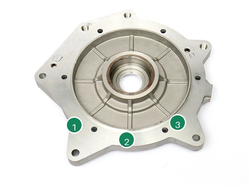
Billet stock often provides machined or controlled external faces that can sit against broad fixture elements. A casting can include draft, flash-removal witnesses, ejector marks, gate remnants, varying cast skin and wall movement from solidification. Broad nest contact can therefore touch different high points from one part to the next. Overconstraint forces the casting to conform to the fixture and releases that strain after machining.
A casting fixture normally uses intentional datum targets or pads rather than assuming the whole nominal CAD surface is present. Clearance around non-locating cast features must include approved process variation. Supports should carry cutting loads without becoming unplanned locators. Clamps need to seat the part consistently, not flatten it.
Fixture Input | Billet Tendency | Casting-Specific Concern |
|---|---|---|
Starting surface | Sawn or previously machined | Draft, texture, flash and local high points |
Shape variation | Stock allowance and straightness | Cavity, lot, shrinkage and warpage variation |
Contact method | Broad jaws or parallels may work | Discrete targets and relief are often safer |
Clamp response | Solid section often resists local load | Thin walls can deflect and spring back |
Chip risk | Known contact surfaces | Cast pockets can trap chips under later loading |
The fixture design should be reviewed with the casting process before tooling release. Adding small cast datum pads, local support bosses or machining allowance can simplify location more reliably than building complex compensation into a fixture after samples arrive.
How to Translate Functional Datums Into Fixture Contacts
The drawing datum reference frame defines how requirements are interpreted; the fixture creates physical contacts that approximate or establish that frame during machining. The two are related but not automatically identical. A primary plane can be simulated by three separated targets, a secondary by two targets and a tertiary by one target in a classic 3-2-1 scheme. Contact locations should maximize stability while avoiding flexible walls, parting lines and variable trim zones.
Datum targets need controlled size and location. A very small button can dig into rough cast skin or sit on a local inclusion; a large pad can bridge shape variation and overconstrain. Replaceable hardened rest buttons can stabilize wear, but the casting must consistently present acceptable material at those points. Target accessibility also matters for cleaning and fixture calibration.
Contact Role | Design Question | Failure Signal |
|---|---|---|
Primary three points | Are they separated and on stiff geometry? | Rocking, clamp flattening or tilted machining |
Secondary two points | Do draft and cast variation change contact? | Part shifts laterally by cavity or lot |
Tertiary stop | Can gate/trim or burr reach the stop? | Variable axial position |
Support point | Does it carry load without locating? | Part lifts from true locators |
Clamp contact | Does reaction pass through support? | Wall deflection or locator slip |
Use blue-check, pressure film, feeler or sensor evidence as appropriate to confirm seating during development. A part-present switch proves presence, not correct contact at every datum. When automated clamps are used, pressure confirmation does not prove the casting was free of chips or seated against the intended targets.
How to Choose As-Cast Pads, Pre-Machined Datums and Supports
As-cast pads can locate the first operation when their position, flatness, draft and trim are designed for fixture contact. They should be robust enough to survive handling and separated from cosmetic or functional surfaces. If the casting process cannot hold the required relationship, a preliminary operation can create machined datums for subsequent precision work.
Rest buttons under stiff ribs or bosses carry cutting forces better than contacts under unsupported skins. Fixed supports should remain slightly clear or share a controlled plane so they do not replace primary locators. Floating or hydraulic supports can advance after the part is located, lock with low disturbance and resist cutting loads. Their sequence, contact force and lock repeatability need qualification.
The machining resource on CNC post-machining for assembly fit explains why final interfaces often need controlled machining. Fixture contacts should be selected from the same functional relationship, not from whichever cast wall is easiest to reach.
How Clamp Force and Reaction Path Distort Thin Castings
A clamp applies force to seat and resist the part. If its reaction does not pass through a locator or support, the casting bends between contacts. The tool then machines the deflected shape. In-fixture measurements can appear correct; after unclamping, springback changes flatness, bore position or sealing-face relationship.
Use the minimum force that prevents motion under the worst credible cutting load, with margin established through testing. Place clamp contact over ribs, bosses or supported sections. Spread contact when local indentation is possible, but avoid large pads that bridge variable cast surfaces. Hydraulic pressure settings should be converted into actual force through cylinder area and mechanism geometry; equal pressure does not mean equal force at different lever positions.
Clamp Issue | How It Appears | Verification |
|---|---|---|
Unsupported wall load | Surface moves as clamp closes | Displacement indicator or scan under staged force |
Unequal clamp sequence | Part seats differently by operator | Sequence trial and contact confirmation |
Excess hydraulic pressure | Good in-fixture dimensions, poor free-state shape | Measure clamped and released conditions |
Clamp on draft | Lateral slip while force rises | Witness marks and displacement study |
Fixture wear | Increasing force or changing seat | Contact inspection and calibration record |
Cutting strategy is part of fixture loading. Heavy roughing, interrupted cuts and long-reach tools create different force directions. Simulate or test the relevant direction rather than validating only clamp closure. Toolpath changes that increase force should trigger fixture review even if the part drawing is unchanged.
How the First Operation Creates Reliable Later Datums
The first operation often converts variable casting references into controlled machined planes, bores or holes for later setups. Those features should be sufficiently separated, rigid and accessible to locate the next operation. Their tolerances must include the relationship to the original functional geometry and enough stock variation to clean up all required surfaces.
Operation two should contact the finished datums without chips, burrs or coating. Use relief around non-contact areas and provide chip escape. If a bore becomes a locating feature, define whether a round pin and diamond pin are used to avoid overconstraint from hole spacing. If two bores control coaxial features, consider locating from one established axis and a clocking feature instead of forcing both onto rigid full pins.
Transfer Element | Operation-One Requirement | Operation-Two Control |
|---|---|---|
Primary face | Flat, clean and related to stock distribution | Three stable contacts and chip relief |
Round locating bore | Size and position suitable for pin fit | Controlled pin wear and insertion |
Clocking hole/slot | Relationship to primary axis established | Diamond pin or directional stop |
Temporary datum pad | Enough stock and stiffness | Removal stage and final inspection defined |
Part identity | Cavity/lot and orientation retained | Poka-yoke prevents reversed loading |
The tolerance stack should allocate casting-to-first-op error, first-op machining error, fixture transfer error, second-op machining error and inspection uncertainty. Quoting only the machine's repeatability ignores the dominant relationships.
How to Accommodate Cavity, Lot and Part-Revision Variation
Measure representative castings from each cavity and multiple lots before freezing nest clearances. Review maximum-material envelopes, parting-line shift, trim variation, ejector marks and warpage. Clearance should prevent unintended contact while retaining enough support and tool access. A fixture that is too tight creates false rejects or clamp distortion; one that is too open can allow chips, wrong orientation or unsupported vibration.
Use part-present and orientation poka-yoke for asymmetric features, but validate sensor logic against broken, flash-heavy and misloaded parts. Cavity-specific offsets can hide upstream variation and create maintenance complexity; use them only with an approved control strategy and evidence that the part remains functionally interchangeable.
A casting revision that moves ribs, draft, gates or ejectors can affect fixture contact even when machined dimensions remain unchanged. Change review should compare the fixture clearance model and physical tryout. The aluminum die casting supplier should provide the variation data needed for this review rather than a single nominal sample.
How to Qualify Fixture Repeatability and the Measurement Boundary
Fixture qualification should separate the repeatability of loading from normal part-to-part casting variation and from inspection error. A repeated-load study uses the same representative part, removes and reloads it through the full clamp cycle and measures features sensitive to fixture location. A multi-part study then tests whether the fixture accepts approved casting variation without shifting relationships or creating distortion.
Measure the released part when the drawing applies in free state. In-fixture probing can support process control but may conceal clamp deformation. CMM inspection should use the drawing datum system and a documented alignment. Guidance on coordinate measuring machines supports inspection planning, but fixture qualification still needs the loading study.
CNC machining accuracy for die cast parts also depends on stock and fixture stability, so dimensional improvement cannot be attributed to the machine alone.
Qualification Test | What It Isolates | Release Question |
|---|---|---|
Empty fixture calibration | Locator position and wear baseline | Is the fixture built to its design? |
Repeated load, one part | Loading, seating and clamp repeatability | Does the same part return consistently? |
Clamp-force sweep | Distortion and slip boundary | What force window is stable? |
Multiple cavities/lots | Part variation interaction | Does normal casting variation fit? |
Chip challenge | Cleaning and false-seating risk | Can production detect and prevent trapped chips? |
Tool-load trial | Dynamic support and clamp adequacy | Does the part move during the real cut? |
Measurement-system analysis should be performed on the inspection method used for release. Fixture repeatability and gauge repeatability are different contributions. A low GRR result does not prove the workholding is stable, and a stable fixture does not make an incapable measurement method acceptable.
Hypothetical Fixture Comparison for a Thin-Wall Housing
Consider a hypothetical cast housing that initially sits in a broad contoured nest. Early samples fit, but later castings rock on changing high points. Hydraulic clamps pull the walls into the nest. A sealing face machines flat while clamped and distorts after release. The team preserves samples and compares contact patterns rather than increasing clamp pressure.
A revised concept uses three primary buttons on stiff cast pads, two lateral targets, one axial stop and low-force floating supports under the cutting zone. Clamps react over supported ribs. Operation one machines a face and two locating features; operation two uses that face, a round pin and a diamond pin. Repeated-load, cavity/lot and free-state studies determine whether the route is acceptable.
This scenario illustrates workholding logic only. It does not claim the pictured casting uses this fixture or that any tolerance was achieved.
What Buyers Should Include in a Casting-Fixture RFQ
Provide 3D casting and finished-part models, 2D drawings, datum scheme, cavity and lot variation data, casting process, machining stock, critical features, expected volume, machine envelope, automation needs, inspection plan and change-control requirements. Ask the supplier to return the locating scheme, support and clamp logic, operation sequence, clearance assumptions and qualification plan.
For integrated CNC machining, the quotation should distinguish fixture design/build cost, prove-out, spare wear components, maintenance and ownership. It should identify whether one fixture family supports all cavities and revisions or whether controlled variants are required.
Supplier Review Item | Evidence to Request | Risk Signal |
|---|---|---|
Location concept | Named contacts and constrained degrees of freedom | “Fits nominal CAD” without variation study |
Clamp path | Reaction through stiff supported geometry | High force used to eliminate rocking |
Operation transfer | Datum creation and error budget | Machine repeatability quoted as part tolerance |
Variation capacity | Cavity/lot envelope and nest clearance | Fixture proved with one hand-selected casting |
Qualification | Repeat load, force, chip and free-state tests | One acceptable first article only |
Maintenance | Wear points, calibration and spare plan | No locator-life or cleaning standard |
A successful casting fixture does not force every part to match nominal CAD. It accepts defined casting variation, creates a stable datum relationship and lets machining forces pass into the fixture without changing the released component.
How Fixture Decisions Affect Cycle Cost and Long-Term Maintenance
Fixture cost is not only the design and build invoice. Loading time, chip cleaning, clamp sequence, probe checks, tool access, wear-component replacement, calibration and recoveries from misloads influence every production batch. A highly adjustable development fixture may accelerate first samples but require too much operator judgment for repeat production. A dedicated fixture can shorten cycle time, yet it must remain tolerant of approved cavity and lot variation.
Buyers should ask which contacts are replaceable, how their position is restored, how clamps are serviced without disturbing locators and what reference verifies the fixture after maintenance. Spare buttons or pins are useful only when their manufacturing tolerance and installation method preserve the qualified frame. A fixture crash requires inspection of the entire load path, not merely replacing the visibly bent clamp.
Lifecycle Item | Cost or Quality Effect | Required Control |
|---|---|---|
Manual loading | Operator time and orientation variation | Poka-yoke, clear access and defined sequence |
Chip cleaning | Non-cutting cycle time and false seating | Relief, evacuation and verified cleaning method |
Wear components | Gradual datum drift | Life limit, master check and controlled replacement |
Hydraulic service | Force and sequence change | Post-service force and displacement validation |
Part revision | Clearance or contact conflict | Digital interference review plus physical tryout |
Fixture storage | Corrosion, impact or lost calibration | Protected storage and restart verification |
Quotations should separate prototype workholding, production fixture, spare parts and validation so buyers can compare equivalent scopes. The lowest initial fixture price can be expensive when every repeat order requires manual shimming, extensive indication or sorting castings that should have fit the approved envelope.
Long-term production records should link fixture identification and revision to the machining program, clamp settings, calibration status and affected lots. This traceability makes dimensional trends actionable: engineering can see whether a change follows a casting cavity, cutting tool, fixture maintenance event or inspection method instead of treating all variation as random machine behavior.
FAQ
How Should Datum Targets Be Placed on Variable As-Cast Surfaces?
How Can Clamps Distort a Thin-Wall Casting During Machining?
When Should a Fixture Use Floating Supports Under a Cast Housing?
How Should First-Operation Datums Be Transferred to Later Setups?
What Tests Qualify a CNC Fixture Before Machining a Production Batch?