Datum Strategy for Cast and Machined Parts: From As-Cast Location to Functional Inspection
Datum strategy for cast and machined parts should connect the way a product assembles and functions to the way the casting is located, machined and inspected. Problems arise when the casting fixture uses one convenient wall, the second CNC setup uses unrelated holes, the CMM applies a best fit and assembly locates from a sealing face and bore. Every report can look acceptable while the final feature relationships drift.
A functional datum reference frame constrains the part according to real interfaces. The manufacturing plan then creates physical target contacts or temporary references that simulate that frame closely enough to produce machining stock and relationships. First-operation machining can create more accurate, durable features for later setups. Inspection should simulate the drawing datum logic rather than fit away the error manufacturing needs to control.
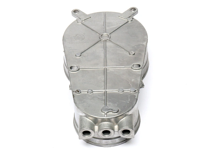
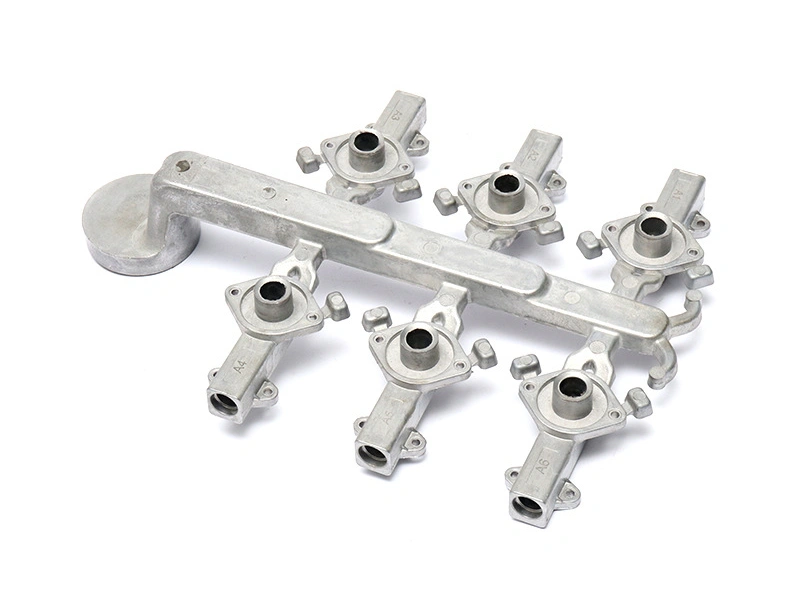
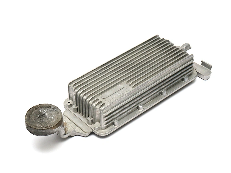
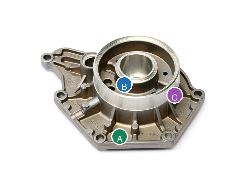
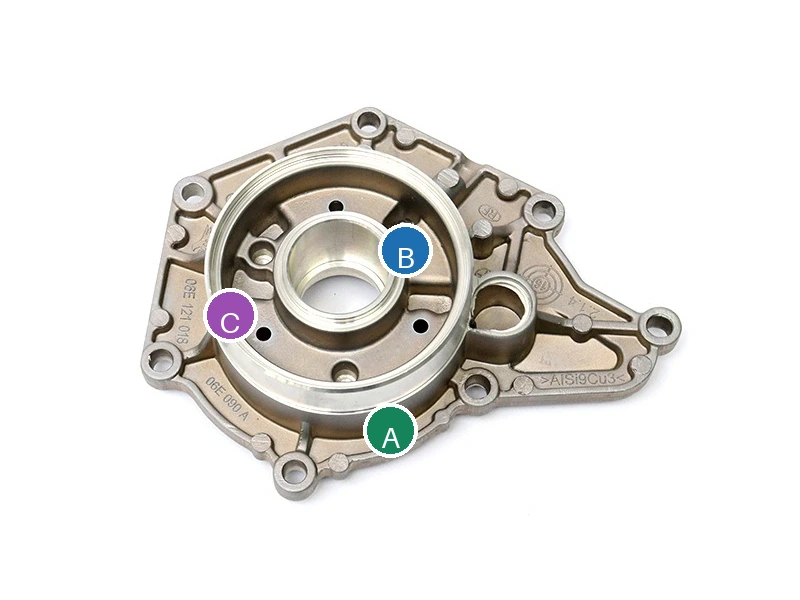
The images show a cast housing from opposing views with several possible contact surfaces. They do not identify actual drawing datums or prove measurement accuracy.
Why Functional, Casting, Machining and Inspection Datums Conflict
The functional datum comes from mating and load interfaces. An as-cast locator is a surface or target available before machining. A machining datum is the reference established in a fixture or program. An inspection datum is how the drawing requirement is simulated during measurement. These can be different physical features, but their relationship must be deliberate and toleranced.
Reference | Purpose | Typical Conflict |
|---|---|---|
Assembly/functional interface | Position part in product | Hard to access in first machining setup |
As-cast targets | Locate operation one | Texture, draft and cavity variation |
Machined setup datum | Locate later CNC operations | Transfer error from first operation |
CMM datum simulation | Evaluate drawing requirements | Best fit or broad surface differs from fixture targets |
Assembly restraint | Represent loaded product condition | Thin casting changes from free state |
Do not call every fixture rest a drawing datum. A support may carry force without establishing location. Conversely, a drawing datum feature can be simulated by several targets rather than full-surface contact. The adopted ASME or ISO standard and released drawing control exact symbols and interpretations.
How to Select a Functional Datum Reference Frame
Start with how the component contacts its mating parts: primary mounting plane, locating bore or pilot, clocking slot, fastener pattern, seal face, bearing axis or other interface. Identify which contacts remove each degree of freedom and which permit required movement or thermal growth. The primary/secondary/tertiary order should reflect function and stability, not drawing convenience alone.
Choose datum features large and stiff enough to simulate repeatably. A thin cosmetic wall can be easy to probe but weak as a functional reference. If several features act simultaneously in assembly, define the applicable requirement and simulation under the chosen drafting standard; do not split them into independent best fits that hide mutual error.
Functional Question | Datum Direction | Evidence |
|---|---|---|
Where does the part seat? | Primary plane or target set | Mating-contact and load analysis |
What establishes center? | Bore, boss or profile-defined axis | Assembly clearance and fit |
What controls clocking? | Slot, hole, flat or target | Connector/port/fastener alignment |
What is allowed to float? | Mobility left unconstrained | Thermal and assembly function |
What changes under load? | Free versus restrained state | Stiffness and assembly validation |
The design review should align 3D model, 2D drawing and assembly intent before casting tooling. Guidance on 3D CAD and 2D drawing conversion is useful, but model translation does not decide datum function.
How Irregular As-Cast Surfaces Become Datum Targets or Pads
An irregular cast surface can serve as a datum feature when its variability is compatible with the function and simulation. Datum targets define discrete contact regions, reducing rocking and preventing a fixture or CMM from contacting random high points over a broad drafted surface. Designed cast pads can provide local stiffness and predictable material.
Place primary targets widely on stiff geometry, secondary targets to control rotation without sliding on draft and a tertiary target away from gate/trim variation. Define target size and coordinates. Relief around non-target regions must include cavity, lot, parting-line and warpage variation. Very small targets can indent soft aluminum; oversized targets can bridge form and overconstrain.
Target Choice | Benefit | Risk to Qualify |
|---|---|---|
Three primary cast pads | Stable plane from defined regions | Pad height and local stiffness variation |
Two side targets | Controlled lateral direction | Draft and trim change contact |
One axial stop | Completes location | Gate witness or burr reaches stop |
Full contour nest | Broad support | Random high-point contact and forced shape |
Preliminary machined pad | More accurate later reference | Extra operation and transfer budget |
Use measured casting envelopes from representative cavities, not nominal CAD alone. The aluminum die casting team should control tooling changes near targets and notify machining/inspection owners.
How First-Operation Datums Create the Transfer Chain
Operation one locates from cast targets and machines references for later operations. A common concept uses a primary face, a round bore and a clocking feature. The face establishes seating, the bore locates center and the clocking slot or second hole controls rotation. A round pin plus diamond pin can avoid binding from hole-spacing variation.
The error chain includes variation of cast target simulation, operation-one cutting, feature measurement, later-fixture locator clearance and wear, operation-two cutting, clamp deformation and final inspection. Machine repeatability is only one contributor. Stock analysis must ensure every critical face and bore cleans up at target extremes.
Chain Stage | Reference | Control |
|---|---|---|
Casting tool | Defined cast pads/target regions | Cavity/lot envelope and trim control |
Operation one | Physical target contacts | Seating, clamp path and stock map |
Created datums | Machined plane/bore/clocking feature | Form, size and relationship inspection |
Operation two | Face plus pins or equivalent | Clearance, wear, chips and repeated load |
Final inspection | Drawing DRF simulation | Qualified alignment and raw report |
How Profile and Position Control Features on Different Faces
Position can control holes, bores and axes relative to a datum reference frame. Profile can control irregular cast or machined surfaces and their relationship to datums. These controls can preserve alignment across different setup directions when the datum scheme is consistent. Over-tolerancing every individual coordinate creates redundant or conflicting requirements.
Drawing review should identify which features function together and whether they share one simultaneous requirement. A bolt pattern and pilot bore may need mutual relationship; separately aligning each group in CMM software can hide pattern-to-pilot error. Casting profile may need a wider zone than machined interfaces while still protecting stock and clearance.
Do not use a best-fit alignment for acceptance unless the drawing explicitly requires that logic. Best fit distributes error and can make a shifted functional interface appear centered. It remains useful for process analysis when reported separately.
How Fixture Simulation and CMM Alignment Should Match
A production fixture physically contacts targets, faces and pins in a sequence. CMM software can simulate those contacts mathematically from measured points or use a soft fixture. The inspection approach should reproduce the intended degrees-of-freedom constraint, contact regions and material-boundary modifiers defined on the drawing.
Probing a broad as-cast surface and fitting a plane is not equivalent to contacting three datum targets. Likewise, aligning to the full measured cylinder can differ from a functional pin contact when lobing or taper exists. The measurement plan should document point locations, fitting method, filters, target order and any restraint.
Machining accuracy after die casting depends on preserving this same datum chain through stock, fixtures and final inspection.
Simulation Item | Production Fixture | CMM/Inspection |
|---|---|---|
Primary contact | Three buttons or qualified surface | Same targets/constraint logic |
Secondary location | Two stops, bore or pin | Feature/target algorithm with same mobility |
Clocking | Stop, slot or diamond pin | Direction constrained without overfit |
Clamp/restraint | Defined force and supports | Free or replicated restraint documented |
Non-datum surfaces | Clearance | Excluded from acceptance alignment |
Guidance on CMM inspection supports method planning. An MSA study should include reloading and re-alignment, because repeated probing without removing the part understates datum-simulation variation.
How Free, Restrained and Assembled States Affect Datum Inspection
Thin castings can change shape under gravity, fixture clamps and assembly bolts. Free-state inspection shows the unloaded component at a defined orientation. Restrained inspection simulates specified contacts and forces. Assembly inspection includes the actual mating stack. The drawing should state the controlled state and restraint rather than allowing inspection to flatten a part until it passes.
Restraint should use the minimum and exact scheme specified. Record support locations, force or torque, sequence and temperature. Measure before and after restraint during development to understand elastic recovery. If a part meets function only when assembled, free-state limits may still be needed for handling and manufacturability.
State | What It Represents | Risk if Undefined |
|---|---|---|
Free state | Delivered unloaded component | Gravity/orientation variation |
Machining-fixture state | Process support and clamp condition | Springback hidden |
Inspection restraint | Specified datum simulation | Excess force forces conformance |
Assembly state | Actual mating and load interfaces | Includes counterpart variation |
Hypothetical Datum Chain for a Cylindrical Housing
Consider a hypothetical cylindrical cast housing whose function uses an end mounting face, central bore axis and one connector orientation. Operation one locates on three designed cast pads, two side targets and one axial stop. It machines the mounting face, pilot bore and clocking slot while verifying stock on the opposite face.
Operation two seats on the machined face, locates with a round pin in the bore and clocks from the slot. It finishes the opposite bore and port pattern. CMM inspection aligns to the same functional face, bore and slot, then reports position/profile across both sides without best fitting each group separately. Free-state and assembly-restraint results are recorded for the thin flange.
This is a hypothetical chain, not a customer drawing or claim about the pictured casting.
What to Include in a Datum-Chain RFQ and Drawing Review
Provide assembly model and interfaces, released 2D drawing and adopted standard, casting and finished models, cavity variation, machining stock, operation sequence, critical features, free/restrained-state requirements, inspection method and expected volume. Ask the supplier to return the cast-target concept, first-operation datum creation, later setup simulation, transfer budget and CMM alignment.
Integrated CNC machining should retain one coordinate logic through programs, fixture drawings and inspection reports. Any proposed datum change needs product-engineering review because it can make results easier to produce while weakening assembly control.
Review Item | Question | Required Output |
|---|---|---|
Functional DRF | Which interfaces constrain the product? | Agreed primary/secondary/tertiary logic |
Cast targets | Can operation one contact repeatably? | Target map and casting controls |
Datum creation | Which features transfer to later setups? | Operation and error budget |
Fixture simulation | How are degrees of freedom constrained? | Locator/support/clamp distinction |
CMM alignment | Does inspection match the drawing? | Program alignment and MSA |
State | Free, restrained or assembled? | Defined force/orientation and report |
A datum chain is successful when the casting tool, fixtures, CNC programs, CMM alignment and assembly all preserve the same functional relationships. Different physical references can be used at different stages, but every transfer must be visible, bounded and verified.
How Datum Strategy Affects Casting Tooling, Stock and Inspection Cost
Datum decisions made after casting tooling can force unnecessary machining allowance, complex fixtures and dense inspection. A designed cast pad can give operation one a stable contact, while a poorly located gate or ejector can occupy the only practical target. If the functional frame is known early, casting engineers can protect target regions, control stock around critical bores and avoid trim lines where locators or gauges need contact.
More machined references do not automatically reduce cost. Each added pad or preliminary feature requires cutting, deburring, cleaning, inspection and operation status. A simple cast target may be sufficient for a broad profile tolerance; a durable machined reference may be necessary for a tight cross-face relationship. Compare the complete chain, not one operation.
Datum Choice | Upfront Effect | Lifecycle Effect |
|---|---|---|
Designed cast targets | Tooling review and local geometry control | Simple first setup if casting remains capable |
Preliminary machined pads | Extra fixture, tool and inspection | Stable later setup and measurement reference |
Full contour location | Complex nest manufacture | High sensitivity to tool/cavity variation |
Functional face/bore DRF | May require staged datum creation | Strong assembly and inspection correlation |
Convenient nonfunctional DRF | Easy fixture access | Extra tolerance and assembly mismatch risk |
Inspection cost also follows datum clarity. A stable DRF can use repeatable fixtures and shorter CMM programs. Ambiguous targets, alternative alignments and independent best fits create engineering review on every borderline result. Tolerance should be allocated where function needs it rather than spent compensating for an avoidable reference mismatch.
How to Control Datum Changes Across Revisions and Suppliers
A datum change can alter stock cleanup, fixture contact, machine coordinates, tool access, CMM alignment, functional gauge design and historical capability. It is not a drawing-symbol-only edit. Before release, compare old and proposed frames on actual assemblies and representative castings. Identify which existing data is no longer comparable.
Suppliers should not substitute an easier setup datum and transform results back mathematically without approval. The transformation may be suitable for tool programming but does not eliminate uncertainty between the manufacturing frame and drawing frame. Reports must evaluate final requirements from the released DRF.
Change Event | Review | Revalidation |
|---|---|---|
Casting tool repair near target | Contact region and stock envelope | First-op seating and transfer |
Datum feature reordered | Mobility constraints and functional intent | Fixtures, gauges and CMM programs |
Machined bore size/fit changed | Locator clearance and simulator behavior | Repeated load and feature positions |
New inspection supplier | Alignment, fitting and restraint | Correlation on shared samples |
Mating component revision | Functional interfaces and assembly mobility | Assembly and datum-function evidence |
Maintain a datum-chain diagram under revision control showing casting targets, operation references, final DRF, inspection simulation and assembly contacts. This compact record lets tooling, CNC and quality teams see how one change propagates. It also keeps repeat orders from reviving an obsolete fixture or CMM alignment.
Which Datum-Strategy Warning Signs Buyers Should Question
Warning signs include a quote based only on nominal CAD with no cast-target discussion, fixture screenshots without constrained degrees of freedom, CMM reports labeled “best fit,” dimensions reported from different local alignments, and thin parts inspected under undocumented clamps. Another warning is a supplier claiming machine accuracy guarantees cross-setup position without an error budget.
Buyers should request one example part traced from as-cast seating through operation one, operation two and final CMM. The supplier should be able to explain each physical contact and mathematical constraint, identify wear and cleaning points, and show how free-state or restrained results relate to assembly.
Final records should identify the datum-chain revision used for casting approval, CNC programs, fixture calibration and CMM evaluation. Without that shared identity, a repeat order can combine a current drawing with an obsolete setup or inspection alignment and produce internally consistent but functionally incomparable data.
FAQ
When Should a Cast Surface Be a Datum Feature Instead of a Machined Pad?
How Do Datum Targets Reduce Rocking on Irregular Cast Surfaces?
What Is Datum-Transfer Error Between First and Second Machining Operations?
How Should CMM Alignment Replicate the Production Fixture Datum Scheme?
When Should a Thin-Wall Casting Be Inspected Free-State or Restrained?