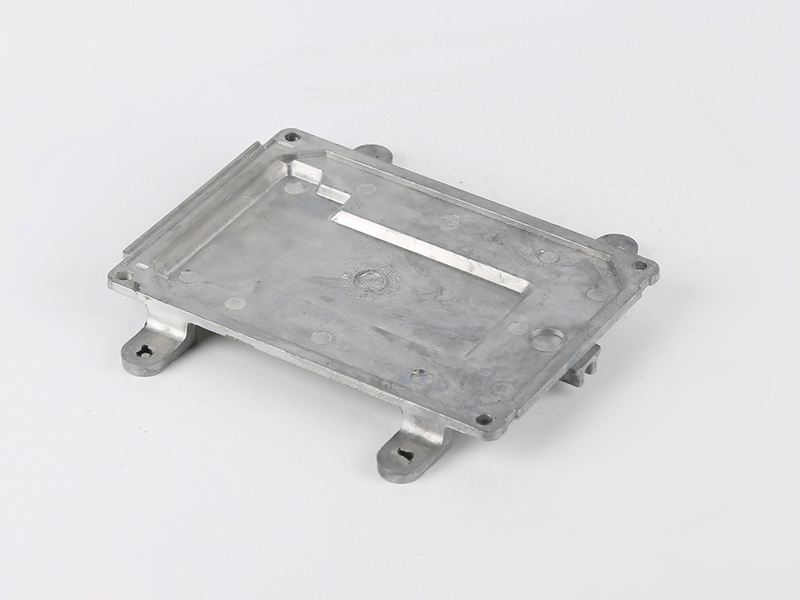
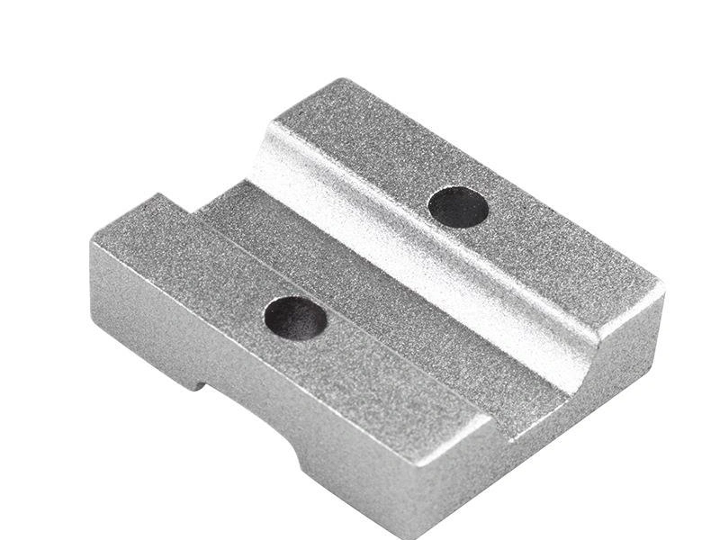
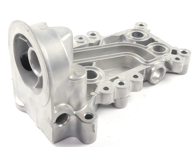
What Design Details Should Be Confirmed Before Machining Cast Parts?
Before machining a cast part, confirm the final datum system, machined surfaces, local stock, tolerances, cutter and fixture access, threads, sealing requirements, coating state and inspection method. Also identify how the raw casting will locate in the first setup. Without both the blank reference and final drawing references, a machine can hold individual dimensions yet place them incorrectly relative to the casting or assembly.
Define the raw and finished states
The supplier needs to know whether each model or dimension represents the casting or the completed part. Mark machined faces and provide final sizes separately from cast targets. A controlled stock model is useful where several surfaces receive different allowances. Do not expect a machine shop to infer stock by comparing two unlabeled CAD files.
Material specification and condition also belong in the release. Alloy, heat treatment where applicable and prior processing can affect blank distortion, cutting response and final properties. Any requirement still under evaluation should be identified as open rather than silently replaced by a supplier assumption.
Input to confirm | Manufacturing decision it controls | Evidence at approval |
|---|---|---|
First-setup cast locators | Fixture contact, clamping direction and blank-envelope relationship | Repeat location without rocking, damage or unacceptable wall shift |
Final datums and geometric controls | Setup sequence, dependent feature machining and inspection alignment | Results evaluated from the drawing datum reference frame |
Stock by machined zone | Cast target, roughing depth, finish pass and cleanup margin | Representative blanks clean up without excess removal |
Finish and masking state | Operation order and protection of holes, threads and mating faces | Final dimensions and appearance after the specified finish |
Functional acceptance | Gauge, measurement, leak test or assembly verification | Agreed report from the state in which the part is delivered |
Connect as-cast location to final datums
An as-cast pad can locate the first CNC operation, but it does not become a final datum merely because the fixture touches it. Show which initial operation creates the machined plane, bore or hole that will reference later setups. Then check whether that sequence preserves wall thickness and positions precision features relative to relevant cast geometry.
Clamping must be practical. Identify thin walls, draft surfaces, ejector marks, parting flash and areas that cannot accept clamp load. The fixture should provide support close to the cutting force without distorting the part. Cutter access, spindle clearance, tool length, chip escape and probing access can drive small geometry changes before casting tooling is frozen.
Assign stock with internal quality in mind
Allowance must cover local casting variation and expected distortion, but excess is not automatically safer. It increases cutting time and may uncover subsurface porosity. Review gate, overflow and thermal regions against deep bores, threaded ports and sealing lands. If a machined area crosses a pressure boundary, define the finished-part leak or pressure test instead of relying on the appearance of the raw casting.
Validate stock on representative blanks from the intended process. Record partial cleanup, wall shift and newly exposed discontinuities. The focused guidance on planning machining allowance for cast parts explains why project evidence is more useful than a universal stock value.
Specify features in functional terms
For holes, state diameter, depth, position, whether they are through or blind, and any break-through restrictions. For threads, state the system, class or tolerance, usable depth, entry treatment, insert requirement and gauge method. For bores, define required size, form, texture and relationship to other features. Do not assign concentricity or tight position simply because it sounds precise; tie controls to the mating design.
For sealing faces, identify the seal type, contact area, flatness and surface-texture requirement, as well as interruptions that are permitted or prohibited. A generic polished finish is not enough. The machining pattern, gasket material, bolt loading and operating condition determine what the interface needs, subject to the product engineer's approval.
State when inspection occurs
Powder coating, plating, anodizing, blasting, heat treatment, insert installation and assembly may change dimensions or damage an accepted surface. Specify masking and whether dimensions apply before or after finish. If an insert load can distort a bore, or coating can reduce its effective size, inspect after that operation as well as at the process stage needed for control.
Define the measurement method for drawing-critical features. A CMM may suit datum relationships and position; thread gauges, surface instruments, leak equipment or functional fixtures address other risks. State first-article scope, production sampling and the records expected with shipment. The inspection plan should distinguish blank-control measurements from final acceptance.
Send a complete machining RFQ
The RFQ should include controlled 3D and 2D data, revision, material, cast and final states, annual and batch quantities, machined-area map, datum structure, tolerances, threads, edge conditions, finish, masking, cleanliness, tests and packaging. Provide mating-part information where fit cannot be understood from the component drawing alone.
Request the proposed blank-location scheme, setup sequence and list of characteristics verified after all value-adding operations. Early engineering review should close assumptions before tooling and fixtures become expensive to change. Clear design details do more than improve quotation accuracy; they make the casting, CNC and final inspection plans refer to the same component.