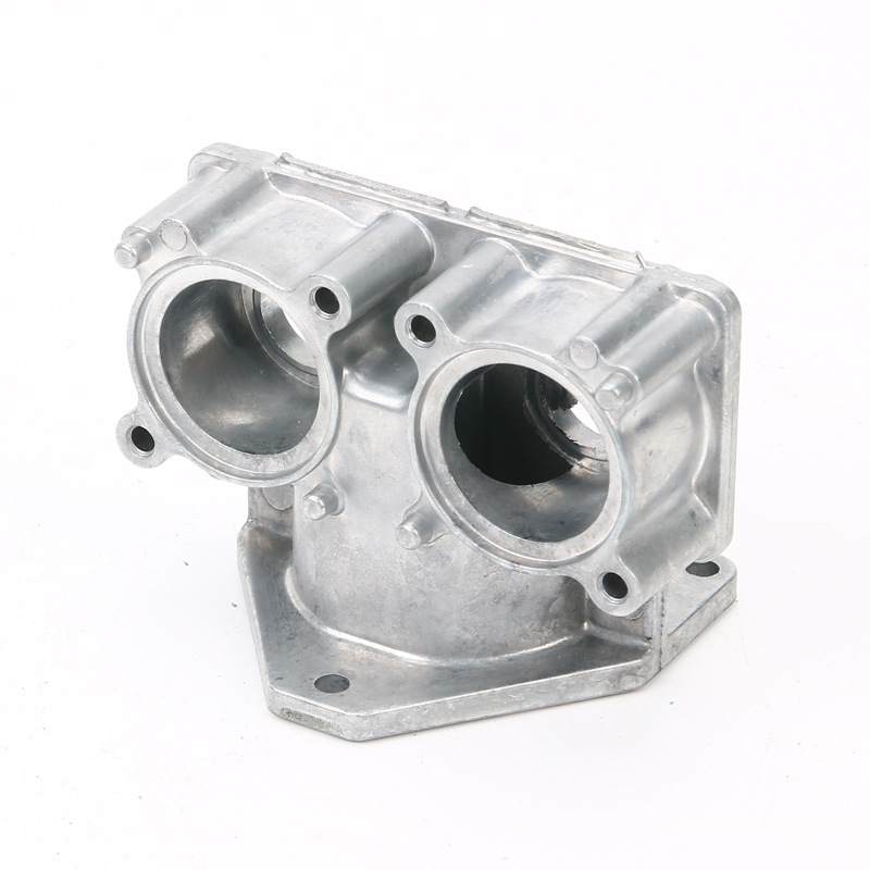
Innovative Design for Custom Metal Casting Parts
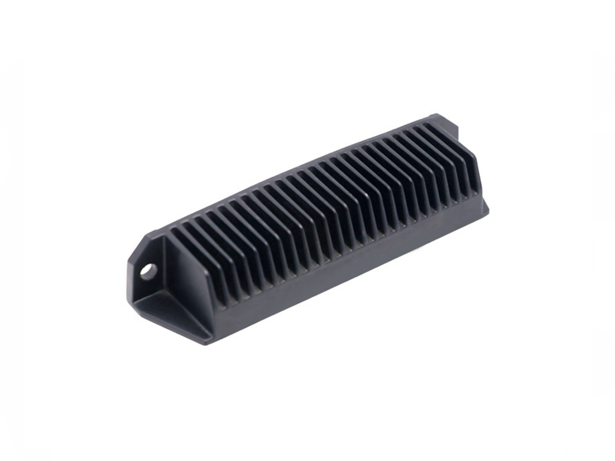
Innovative design for a custom metal casting part means creating more function with geometry that the selected alloy, casting process, die, and inspection plan can reproduce. The useful innovation may be a consolidated housing, a lighter ribbed bracket, an integrated heat path, or a datum scheme that reduces machining. It is not an unusual shape added for its own sake. A concept is production-ready only after its thin sections can fill, heavy sections can solidify without unacceptable shrinkage, the part can leave the tool, and its critical features can be measured.
This distinction matters before an OEM releases tooling. A CAD model can satisfy assembly space and still create opposing requirements for metal flow, ejection, sealing, machining, and coating. Resolving those conflicts early is the purpose of casting design engineering. The work joins product intent with metal casting process behavior instead of treating the drawing as a fixed object that a foundry must somehow reproduce.
Start with the job the casting must do
The first design decision is not the fillet radius or draft angle. It is the hierarchy of product requirements. A pressure housing may put leak integrity and sealing-flatness control ahead of cosmetic texture. A heat-dissipating enclosure may prioritize a short thermal path, fin access, and controlled machining around interface pads. A structural bracket may be governed by load direction, joint stiffness, fatigue locations, and mass. When every feature is marked equally critical, the tool and inspection plan become expensive without clarifying what actually protects the product.
A practical requirement map separates four groups. Functional requirements cover load, temperature, corrosion exposure, electrical behavior, pressure, and service life. Interface requirements identify datums, fastener locations, bores, connectors, gasket lands, and assembly clearances. Appearance requirements define visible zones, texture, coating, allowable witness marks, and areas hidden after assembly. Production requirements state forecast volume, ramp pattern, target cost context, traceability, and validation level. These groups let the designer decide which surfaces should be cast, machined, protected from ejector marks, or moved away from a parting line.
The drawing should also distinguish a performance target from a prescribed solution. For example, specifying the load case and allowable displacement gives the design team room to change ribs or section shape. Requiring a solid wall of a particular thickness may lock in thermal mass without proving stiffness. Likewise, a leak-rate requirement is more useful than the vague phrase "no porosity" because every casting process can contain discontinuities; the relevant question is whether their size, location, and connectivity affect the sealed boundary.
Connect alloy, process, and geometry
Material cannot be selected from a strength value alone. Alloy chemistry affects fluidity, freezing behavior, hot-tear sensitivity, corrosion response, thermal conductivity, machining, and the finish that can be applied. The casting route then changes how those properties interact with the part. High-pressure die casting favors near-net-shape production and integrated detail, while gravity or low-pressure routes may suit different section sizes, alloys, or integrity requirements. The right combination depends on the actual geometry and acceptance plan.
For example, A380 aluminum is commonly considered for pressure-die-cast housings where castability and a useful balance of properties matter. An aluminum-silicon option such as AlSi12 may enter the comparison when filling behavior or chemistry limits are important.
Zamak 5 may suit compact components that need fine detail and a different strength or finishing balance. These are screening directions, not substitutions. The governing alloy designation, temper or heat-treatment condition where relevant, test method, and approved equivalent must be stated on project documents.
Copper and brass alloys bring another set of thermal, electrical, corrosion, density, temperature, and tooling considerations. A buyer evaluating copper and brass casting alloys should not transfer aluminum geometry rules into the new material. A feature that fills reliably in one alloy and process may require a different wall, gate, radius, or secondary operation in another. Comparison should use the same duty cycle and acceptance criteria, then verify castability with the proposed tool concept.
Design question | Evidence needed before commitment | Likely decision | Risk if left implicit |
|---|---|---|---|
Must a thin region fill around ribs or lettering? | Alloy and process proposal, flow path, venting concept, simulation or trial evidence | Adjust local section, gate access, rib direction, or detail | Cold shuts, incomplete detail, trapped air |
Does a heavy boss carry load or only locate a fastener? | Load case, section review, solidification result, machining allowance | Core the boss, add support ribs, or separate the function | Shrinkage, sink, distortion, exposed voids after machining |
Is an internal feature worth a slide or loose core? | Tool-motion study, cycle and maintenance effect, alternate assembly concept | Accept tool action, redesign the feature, or machine it | Tool complexity, flash, wear, inaccessible inspection |
Must a dimension be achieved as cast? | Datum plan, tolerance stack, process capability study plan, gauge method | Keep as cast, relax the requirement, or machine the feature | Unstable assembly fit or unnecessary machining cost |
Will the part receive coating or plating? | Service environment, finish specification, masking zones, surface-defect limits | Select compatible alloy and pretreatment; define cosmetic zones | Adhesion failure, dimensional conflict, visible defects |
Build load paths with castable features
A cast part becomes lighter and stiffer through load-path design, not through indiscriminate thinning. Start by identifying where loads enter, how they travel to mounts, and where geometry changes create local stress. Ribs can connect those paths while keeping the main wall closer to a uniform thermal mass. Their direction should support both structural work and metal flow. Ribs that terminate abruptly at an isolated thick junction can solve a finite-element problem while creating a solidification problem.
Bosses deserve the same scrutiny. A fastener boss needs enough material for its load and thread strategy, but a fully solid post may hold heat and shrink later than the surrounding wall. Coring the boss, tying it into walls with appropriately shaped ribs, and giving the base a gradual transition often creates a better casting. The exact proportions are project variables because alloy, process, boss height, tool access, and load all matter. They should be confirmed through DFM, analysis, and trials rather than copied from a generic rule.
Fillets are functional transitions. Internal corners with no radius impede smooth filling, concentrate stress, and create a sharp thermal junction in the die. Very large fillets can also add local mass. The designer therefore chooses a radius that supports flow, strength, tool manufacture, and neighboring feature clearance. A marked-up section view is often more useful than a single global note because a sealing land, rib root, and cosmetic edge do not have the same purpose.
Use wall thickness as a controlled variable
Uniform walls are a sound starting point, but functional castings rarely remain perfectly uniform. The engineering task is to make every variation intentional. A thicker region may provide a machining stock allowance, carry a threaded insert, spread a clamp load, or form a heat sink base. The transition into and out of that region should be gradual, and the foundry should examine whether the extra mass changes fill sequence, cooling, or distortion. Hollowing a heavy area, moving material into ribs, or changing part orientation may preserve function with lower defect risk.
Minimum-wall statements are especially easy to misuse. A supplier may fill a small local feature under one set of conditions without being able to reproduce a large thin panel with the same nominal thickness. Flow length, projected area, gate distance, alloy temperature window, venting, die temperature, surface requirement, and adjacent mass all affect the result. A credible review describes the actual thin region, shows how metal reaches it, and defines what trial evidence will authorize production.
Design for tool motion and maintenance
Every surface must be formed and released. The parting line establishes the primary tool opening; holes, pockets, clips, and reverse features that do not align with that motion may require slides, lifters, collapsible elements, soluble cores, or machining. Each additional tool action can be justified, but it adds interfaces where flash, wear, alignment variation, and maintenance can occur. An innovative part often removes actions by changing feature direction or by making two features share a tool movement.
Draft is not one universal angle applied to the whole model. Required release allowance depends on draw depth, alloy, surface texture, tool finish, feature type, and whether the surface lies on the moving or fixed half. Deep ribs and textured walls usually need different consideration from a short smooth boss. The DFM record should mark the draw direction, no-draft functional zones, permitted dimensional change, and surfaces where drag marks are unacceptable.
Ejector pins, overflows, gates, and trim remnants are part of the product design even though they begin as tooling decisions. Their witness marks must not occupy a gasket track, bearing seat, visible face, or locating datum unless the downstream plan accounts for them. The tool and die-making review should therefore happen while surfaces can still move, not after the industrial design has frozen every cosmetic boundary.
Tool maintenance also changes the preferred geometry. A fragile standing steel feature may reproduce a narrow slot but be vulnerable to heat checking or damage. A deep pocket may be difficult to polish or repair. Replaceable inserts can isolate wear or simplify service, yet their interfaces affect cooling and witness lines. Buyers should ask which inserts are replaceable, how critical cavities are identified, what maintenance records will be kept, and how dimensions are requalified after repair.
Treat flow, solidification, and venting as one system
Molten metal needs an uninterrupted route into the cavity and displaced gas needs an exit. A visually balanced part is not necessarily balanced for filling. Flow may split around a core, meet at a cold junction, or push air toward a blind pocket. Gates and overflows must be considered with wall changes, ribs, holes, and cosmetic faces. Moving one boss can change where flow fronts join; rotating a rib can either guide metal or form a barrier.
Solidification analysis asks a related but different question: where will the last liquid metal remain, and can the process compensate for its contraction? Thick intersections, isolated pads, boss bases, and abrupt section changes are typical review targets. The response depends on the casting route. It may involve geometry changes, local cooling, feeding strategy, pressure transfer, or a different orientation. The design team should record which defect mechanism each change addresses so that a later CAD revision does not quietly restore the original risk.
Simulation is useful when its assumptions and decisions are visible. A colored plot alone does not approve a design. The model needs the proposed alloy, process inputs, initial and boundary conditions, gate and vent geometry, and a defined result to evaluate. The review should compare alternatives, identify risk zones, and state what will be confirmed by tool trials. This approach makes simulation a decision record rather than a presentation image.
Reserve machining for functional interfaces
Near-net-shape design does not mean every dimension should remain as cast. Bearing seats, precision bores, sealing lands, threaded features, and datum interfaces may need post-casting CNC machining. The designer should reserve stock intentionally, establish a stable locating scheme, and avoid cutting into a region where predicted or observed porosity would compromise function. Machining drawings also need to define whether dimensions reference cast datums, machined datums, or an assembly coordinate system.
Reducing machining starts with separating critical interfaces from general geometry. A tolerance that protects bearing alignment may be valuable; applying the same tolerance to an external non-mating wall is not. Profile tolerances can sometimes control a functional surface more clearly than many independent plus-minus dimensions. However, the chosen GD&T must match how the part will be fixtured and measured. A requirement that cannot be gauged repeatably is not production control.
Machining trials provide evidence about more than dimensions. They reveal cutting behavior, burr formation, stock consistency, and subsurface discontinuities exposed at bores or faces. If a leak path or highly loaded feature will be machined, the casting validation plan should inspect that condition rather than relying only on an unmachined sample. Acceptance can then link casting parameters, machining results, and the relevant pressure, dimensional, or material tests.
Plan surface finish before freezing geometry
Finish requirements influence alloy choice, parting-line placement, ejection, gate removal, polishing access, and dimensional allowances. A cosmetic powder-coated cover, a plated zinc control, and an uncoated internal bracket do not share the same surface plan. The drawing should identify viewing direction, appearance zones, permissible flow or parting-line marks, texture reference, color or gloss method, coating thickness where it affects fit, and masking areas.
Surface treatment cannot be expected to hide structural defects. Blisters, exposed porosity, cold laps, and poorly trimmed flash need process or design correction. Conversely, a sound casting may still fail appearance review if the buyer and supplier compare it under different lighting or at different distances. A signed visual limit sample and an agreed inspection setup turn subjective language into a usable control.
Threads, grounding pads, gasket lands, and close-tolerance holes may need masking or post-finish machining. Their design should allow racks, contacts, drainage, and handling without damaging the visible face. Finish trials should use the proposed alloy and casting surface because a machined prototype or printed model cannot reproduce casting skin, release-agent residues, porosity, or pretreatment response.
Validate the design in stages
Different prototypes answer different questions. A 3D-printed prototype can check envelope, ergonomics, connector access, and assembly sequence. A machined sample in a nominally similar alloy can support early load or thermal exploration. Neither proves die fill, as-cast properties, surface condition, or production distortion. Those questions require representative casting trials and a controlled measurement plan.
Before tool release, the team should close open items in a traceable DFM record. Typical entries include draw direction, parting line, slide actions, gate and overflow zones, ejector locations, draft exceptions, machining stock, datums, critical dimensions, cosmetic surfaces, and simulation actions. Each deviation from the product drawing needs an owner and approval. This record is more valuable than verbal agreement because it remains available when tooling, quality, and purchasing teams change.
Tool trials should then progress from learning to evidence. Early shots establish a stable process window and reveal fill, ejection, trim, and distortion behavior. Dimensional layout confirms the datum system and identifies tool corrections. Machined and finished samples test downstream operations. Functional samples verify load, leak, thermal, electrical, corrosion, or assembly requirements defined by the product. Production release should depend on agreed results, not simply on receiving parts that look complete.
Inspection method selection follows the failure mode. Coordinate measurement may suit datum relationships and accessible geometry. Scanning can compare complex surfaces but needs an agreed alignment and interpretation. X-ray or computed tomography may investigate internal discontinuities where the part, thickness, resolution, and acceptance rule make the method meaningful. Sectioning, pressure testing, material analysis, coating tests, or mechanical tests may be more direct for another risk. The buyer should define what evidence is required, while the manufacturing team confirms method limits and sampling.
Control change with a design decision record
Innovation rarely arrives in one revision. The risk lies in changing geometry without preserving why an earlier feature was added. A rib may look redundant after an assembly update but still control flow or ejection. A pad may appear oversized but carry machining stock and a datum target. The change process should identify affected tooling surfaces, simulation assumptions, gauges, machining fixtures, finish masks, inspection programs, and approved samples.
A concise decision record can list the issue, options considered, selected change, evidence, affected documents, and remaining validation. This keeps product, supplier, and quality teams aligned without freezing development. It also improves later cost reduction: the team can distinguish a feature that is truly required from one retained only because its origin was forgotten.
Prepare an RFQ that supports real design work
A useful RFQ lets the casting supplier evaluate the complete problem. Send a revision-controlled 3D model and drawing, annual and lifetime volume assumptions, lot pattern, current material specification, service environment, load cases, operating temperature, pressure or sealing duty, mating components, critical-to-quality features, finish and appearance zones, regulatory or documentation needs, and the desired validation schedule. Identify which requirements are fixed and where alternatives are welcome.
For an existing product, add failure history, inspection data, assembly issues, current process, and cost drivers. If a bore exposes porosity, show its location and machining depth. If a cover warps after coating, state the coating cycle and flatness measurement condition. Actual evidence gives the DFM team a mechanism to investigate; statements such as "improve quality" or "make it cheaper" do not define an engineering target.
The quotation should separate assumptions from commitments. It should identify the proposed alloy and process, tooling concept, included secondary operations, sampling and test scope, critical open questions, and changes needed before release. Final wall limits, tolerances, tool life, cycle, yield, and delivery depend on geometry, alloy, cavity strategy, finish, quality plan, and validation results. They should be confirmed for the reviewed project rather than presented as universal capability numbers.
A practical review before tool release
A custom metal casting design is ready to advance when its product logic and manufacturing logic agree. The team should be able to answer where loads travel, how metal fills and gas exits, where the last hot regions occur, how the part releases, which marks are acceptable, what will be machined, how the part is located, and how every critical requirement will be verified. Unanswered questions should remain visible as trial actions, not be hidden behind a general approval.
The strongest design is not necessarily the thinnest, most integrated, or most geometrically complex. It is the design that delivers the required function with controlled process risk and evidence that purchasing and quality teams can audit. Early design-for-manufacturability review, followed by disciplined simulation and representative trials, gives original product ideas a credible path into repeat production.
Frequently Asked Questions
What are the best practices for designing parts with varying wall thicknesses in metal casting?
How early should I involve Neway's engineering team in the design phase?
What simulation tools are used to validate custom casting designs?
Can I modify an existing part design to make it suitable for die-casting?
How does alloy selection affect design constraints and casting precision?