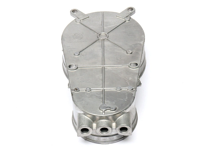
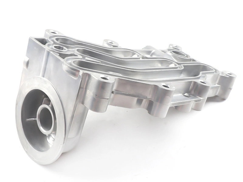
Casting and Machining Service for Precision Custom Metal Parts
A casting and machining service produces a near-net-shape metal blank, then CNC-machines only the interfaces that need controlled size, location, form or surface condition. It is a sound route for precision custom metal parts when casting can carry the bulk geometry and a documented datum chain can carry functional requirements from the blank through machining, finishing and final inspection. Casting alone does not make the delivered component precise, and machining cannot rescue a poorly planned or internally unsound casting.
Buy a finished component, not two disconnected processes
The useful purchasing unit is the part in the condition required by the next operation: correct alloy and temper or material condition, finished dimensions, specified coating, clean threads, installed inserts where applicable, functional test status and agreed documentation. A raw casting quote and a CNC operation quote do not describe that unit. They omit the interfaces where stock, datums, defects and revisions cross from one process to another.
A combined route starts with a functional drawing and works backward. The team identifies sealing faces, bearing seats, locating holes, threaded bosses, electrical contacts and mounting planes. It then decides which geometry can remain as cast, which features need machining, and what evidence will release the finished part. That is the practical meaning of integrating metal casting with post machining.
The casting method is project-specific. High-pressure die casting may suit repeat aluminum or zinc housings with thin, intricate geometry. Sand casting may be more sensible for larger parts, lower demand or alloys outside the usual pressure-die-casting range. Other routes may fit different size, material and internal-geometry needs. The machining plan must be based on the selected casting process and its realistic blank variation, not on a generic idea of a casting.
Material condition is part of the route
An alloy name alone does not close the material requirement. The governing grade, chemistry limits, casting route and any heat treatment or stabilization affect machinability, distortion, corrosion behavior and final properties. A grade commonly supplied as a sand or permanent-mold casting should not be assumed to suit high-pressure die casting just because both routes use aluminum. Confirm the recognized material designation and delivery condition against the product requirement.
Ask how material identity is verified and how heat or lot records follow the casting through machining. If a mechanical property or conductivity value is important, define the specimen, location, condition and test method. Published nominal properties are useful for screening, but the released part needs project-specific evidence appropriate to its process and geometry.
Separate as-cast features from machined features
Precision should be assigned by function. Ribs, external contours, non-mating walls and many pockets can often remain as cast. A gasket face may need controlled flatness and texture; a bearing bore may need diameter, form and position related to another bore; a tapped hole may need a true location and usable thread depth. Applying machining tolerances to every visible surface spends machine time without necessarily improving the assembly.
The drawing should make this distinction unambiguous. Use machined-surface symbols, datum feature identifiers, geometric controls and notes tied to final condition. Avoid an undifferentiated title-block tolerance that accidentally forces inspection or machining of nonfunctional cast geometry. The die-casting tolerance planning guide expands on which requirements need explicit marking before tooling and CNC planning.
Feature relationship | Likely process decision | Evidence to request |
|---|---|---|
Non-mating rib or exterior wall | Leave as cast if draft, profile and appearance are acceptable | Approved sample, visual standard and any profile check required by function |
Mounting plane related to locating holes | Machine in a controlled setup or a proven sequence | Flatness and hole-position results referenced to drawing datums |
Paired bearing seats | Bore from a shared machining reference where geometry permits | Diameter, form and mutual alignment results using an agreed method |
Gasket face over a pressure boundary | Machine with stock and internal-quality planning around the face | Surface result plus finished-part leak or pressure test when specified |
Threaded boss | Cast the boss; drill and tap or thread mill to final requirement | Thread gauge result, usable depth and boss integrity check as applicable |
Build a datum chain from the blank
An as-cast locating surface and a final drawing datum are not automatically the same thing. The first machining setup needs repeatable cast features that seat the blank without rocking and without distorting a thin wall. That setup creates one or more machined references. Later operations and final inspection can then use those controlled references to establish the functional datum system.
This distinction matters because a fixture can hold every blank consistently and still produce the wrong relationship to the casting envelope. Suppose a housing is clamped from an irregular exterior pad while a bearing bore must be centered within an internal wall. If the pad-to-wall relationship varies, the bore may meet its own diameter but break through one side or leave uneven wall thickness. A fixture concept must therefore control both the machined feature and its relationship to relevant as-cast geometry.
Datum planning also determines setup count. Features machined in one clamping share a stronger process relationship than features created after the part is released and relocated. That does not mean every feature belongs in one setup; cutter access, distortion, chip evacuation and fixture stiffness may make multiple setups more stable. The drawing requirement, fixture scheme and inspection alignment should be reviewed together before the tool design is frozen.
Set machining stock by surface and process
Machining allowance is not a universal number added to every face. It must cover the expected local blank variation, draft, parting mismatch, distortion and fixture location error while leaving enough material for the intended cutting sequence. The correct amount depends on alloy, casting route, part size, wall distribution, tool condition, ejection and where the surface sits relative to gates, overflows and thermal concentrations.
Too little stock causes partial cleanup, interrupted sealing lands or a final feature outside position after the blank is located. Too much stock adds cycle time and cutting load. On castings susceptible to internal pores, deeper removal can also expose discontinuities that were beneath the original skin. Adding stock is therefore not a harmless insurance policy. Confirm it by reviewing blank measurements and machining representative castings, then update the casting and CNC control plans with the observed result.
Stock should be visible in the manufacturing model or drawing. Identify final dimensions separately from cast target dimensions, and state whether the CAD model represents the casting, the machined part or both configurations. This prevents the toolmaker from treating a final face as an as-cast surface and prevents the machine shop from assuming material exists where none was designed.
Place casting features with the machining result in mind
A machined face can reveal what the casting skin concealed. A sealing land, hydraulic passage or threaded port located in a region prone to entrained gas or shrinkage deserves more than a cosmetic cleanup operation. Gate and overflow positions, vents, local section transitions and thermal balance should be reviewed against the machining map. The target is sound material through the depth that will remain after machining.
Visual inspection of an unmachined blank cannot qualify a pressure boundary hidden below its surface. Radiography or computed tomography may be useful for development or selected internal risks, but the method, sampling and acceptance criteria must match the defect size, material thickness and function. The available X-ray inspection overview explains the role of radiographic evidence; it does not replace a part-specific acceptance plan.
When leakage is the actual risk, validate the machined and otherwise completed pressure boundary with the agreed leak or pressure test. State the medium, pressure or vacuum condition, stabilization, allowable result, test stage and sampling. A generic claim that the casting is dense is not an acceptance criterion.
Choose an operation sequence that protects the final state
The route may include trimming, shot blasting, heat treatment, straightening, rough machining, stress relief, finish machining, cleaning, coating, insert installation and assembly. Their order changes dimensions and risk. Blasting can damage a protected machined face. Heat treatment or aggressive stock removal can release residual stress. Coating can close a bore or change a mating stack. Pressing an insert can distort a nearby thin section.
Sequence the process around the feature that has to survive. Roughing before a stabilizing operation may be appropriate for a casting that moves after stock removal; another part may require final machining after coating on selected interfaces. There is no universal route. What matters is that the final acceptance stage occurs after any operation capable of changing the accepted characteristic.
For example, inspect a precision bore after a coating operation if coating enters or builds near that bore. Recheck a flange relationship after an insert or subassembly is pressed in if the load can distort it. Protect clean sealing faces during blasting and transport. The broader surface-finishing overview is useful for identifying process interactions, but coating type, thickness, masking and acceptance still belong on the project record.
Inspect the datum chain, not isolated numbers
A caliper result on an individual boss says little about whether a part will assemble. Inspection must reproduce the drawing datum reference frame and verify the relationships that carry function. A coordinate measuring machine can evaluate position, profile and orientation when the setup, probe access, alignment strategy and uncertainty are suitable. Dedicated gauges may be faster and more representative for repeat assembly features. Surface texture, thread gauges and functional fixtures cover different risks.
The CMM inspection resource describes coordinate measurement capabilities. Buyers should still define which characteristics appear on first-article and production reports, the sampling plan, measurement state and response to an out-of-control trend. Asking for a CMM report without those decisions can create a long list of dimensions while missing the assembly relationship that matters.
Inspection should also distinguish blank control from final-part acceptance. Blank dimensions protect machining cleanup and fixture location. In-process checks protect tool offsets and sequence. Final checks release the coated or assembled component. Connecting results by material heat or lot, casting batch, die cavity where relevant, machine setup and finish batch gives engineers enough context to locate a failure.
Use first-article evidence to freeze the route
A dimensional report from one hand-finished sample does not validate production. First-article evidence should come from representative tooling, casting conditions, fixtures, CNC programs and downstream operations. Record where a blank sits in its tolerance range, whether every machined zone cleans up, and whether tool access or clamping leaves marks or distortion. For multi-cavity tooling, the qualification plan should address cavity-related variation according to the project risk.
Freeze the accepted route with revision-controlled casting and machined models, fixture references, operation sheets, inspection programs and approved finish standard. Later changes to gates, die inserts, locators, CNC programs or subcontracted processes need review proportional to their effect. This prevents a supplier from reproducing the first-article dimensions by a materially different route that has not passed the same functional evidence.
Compare the combined route with full CNC at equal scope
Casting plus machining often wins when demand is repeatable, the design is stable and most geometry does not need cutting. Full CNC machining often wins during early iteration, at low uncertain demand, or when nearly every surface is precision-machined. Neither conclusion follows from shape alone. The comparison must use the same alloy or approved functional alternative, final dimensions, finish, tests, yield assumptions and delivery scope.
Include casting tooling, fixtures, gauges, validation, raw casting yield, trimming, machining cycle, tool consumption, cleaning, coating, inspection, scrap and change exposure. Include billet size, material recovery, every CNC setup and comparable quality costs on the full-machining route. The CNC machining versus casting comparison provides a route-level framework, while this article focuses on controlling their combination.
Decision input | Evidence before approving casting plus machining | Warning sign |
|---|---|---|
Demand and design state | Forecast scenarios, stable revision and ownership of tooling changes | Tooling justified by an unsupported volume estimate |
Blank capability | Representative cast measurements at locating and cleanup surfaces | One blanket allowance used without local variation data |
Functional machining | Datum sequence, fixture concept, operations and inspection alignment | Machine drawing created after casting tooling is released |
Internal integrity | Risk-based detection and finished-state functional test where needed | Appearance of the raw casting used to approve a hidden pressure boundary |
Delivered cost | Equal scope including finish, inspection, scrap and revisions | Raw casting price compared with a completed CNC part |
Qualify a one-stop supplier by controls, not by the label
One commercial owner can shorten feedback between foundry, machine shop and finisher. It does not automatically improve quality. The benefit exists only when revisions, nonconformances and inspection data follow the part across each handoff. A supplier may operate every process internally, use approved subcontractors, or combine both. Buyers need visibility into the actual route.
During qualification, trace one drawing characteristic from customer requirement to casting stock, CNC operation, inspection method and final record. Review how a tool or program revision is authorized, how mixed revisions are prevented, how outsourced finishing lots are identified, and who has authority to stop shipment. A useful one-stop casting service overview can frame the commercial model, but evidence from the proposed production route should decide approval.
RFQ inputs for a machined casting
A quote is only as reliable as its process scope. Send both a controlled 3D model and a readable 2D drawing, and identify which configuration each represents. Include the material specification and condition, forecast quantities, production life assumptions, cosmetic zones, prohibited gate or ejector areas, and any regulatory or customer-specific requirements that genuinely apply.
Mark all machined surfaces, final dimensions, datum systems, geometric controls, threads, inserts, edge conditions, surface texture and sealing lands. Define coating and masking, cleanliness, assembly interfaces, mating-part information, leak or load tests, inspection reports, sampling, traceability, packaging and delivery state. Where tolerances or test limits are still open, label them for engineering confirmation rather than allowing the supplier to guess.
Questions the supplier should answer
Which cast features locate the first CNC setup, and how is their variation controlled?
Which machined surfaces become datums for later setups and final inspection?
How was stock assigned to each machined zone, and what sample evidence will confirm cleanup?
Could machining expose porosity at sealing, threaded or highly loaded features, and how will that risk be verified?
Which operations occur after dimensional acceptance, and can any of them change fit or function?
What is inspected on the blank, in process and in final delivered condition?
Which operations are subcontracted, and how are revision status, lot identity and nonconformances transferred?
Approve the process chain
A successful casting and machining service does more than add CNC operations to a cast part. It connects the casting envelope to fixture location, machined datums to functional features, internal integrity to material removal, and final inspection to the condition in which the customer receives the component.
Approve the route when representative castings clean up with controlled stock, the datum strategy reproduces the assembly relationship, finishing does not invalidate accepted dimensions, and the agreed evidence releases the completed part. That chain is what makes a precision custom metal component repeatable. The names of the individual processes are only the beginning.
Frequently Asked Questions