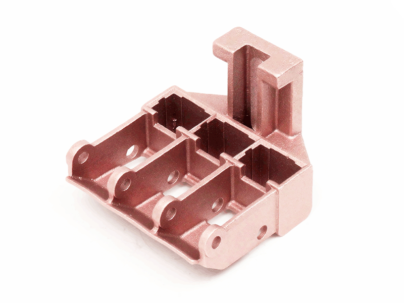
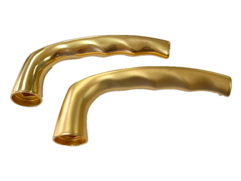
Copper Die Casting Service for High-Conductivity Custom Metal Parts
A copper die casting service can produce high-conductivity custom parts when a named copper alloy is compatible with the selected pressure-casting route and the complete conductive path is designed, machined, finished and tested as one system. Copper content alone does not approve the part. Alloy chemistry, casting discontinuities, section area, contact geometry, plating, fastener load and operating temperature all influence electrical or thermal performance.

Define high conductivity at part level
Electrical conductivity is a bulk material property, but buyers use components, not laboratory coupons. A current path also has length, cross-section, bends, interfaces and heat rejection. A terminal with adequate material conductivity can still run hot if its contact area is small, plating is damaged, fastener preload relaxes or a machined transition leaves insufficient section. Define allowable resistance or temperature rise under the actual current and assembly condition where the product design requires it.
Thermal parts need the same discipline. Alloy conductivity is only one term in the heat path. Contact flatness, interface material, wall geometry, internal channels, convection and mounting pressure may dominate system temperature. Specify heat input, coolant or airflow, boundary temperatures and the measurement locations. A copper die casting service can then assess whether near-net geometry creates enough value to justify the material and tool demands.
Functional target | Part variable | Production evidence | Common false shortcut |
|---|---|---|---|
Low electrical loss | Grade, path length, section and internal continuity | Chemistry traceability and resistance test at defined locations | Using nominal copper content as finished-part evidence |
Stable electrical joint | Contact area, roughness, plating, preload and mating metal | Joint resistance and temperature-rise test in assembly | Testing the loose casting only |
Heat transfer | Alloy, wall path, contact flatness and cooling boundary | Thermal test using stated heat and boundary conditions | Comparing handbook conductivity alone |
Fluid containment | Alloy-media compatibility, porosity zone and machined seal | Leak or pressure test with agreed medium and condition | Assuming corrosion resistance means pressure integrity |
Separate copper, brass and bronze objectives
Copper-base alloys span a wide range of chemistry and behavior. Higher conductivity generally competes with alloying additions used for strength, castability, wear or corrosion response. Brass may be chosen for machinability or a fluid-system requirement; bronze may be chosen for a wear couple or a particular environment. Neither label means high electrical conductivity, and neither establishes suitability for high-pressure die casting.
Start with the controlling specification and exact designation. Confirm whether the grade is supplied and processed as a casting alloy in the proposed route. Some familiar copper grades are primarily associated with wrought, forged or other casting processes. Similar composition names across standards are not automatic equivalents. The copper-alloy directory is a shortlist, not a substitution approval.
High-conductivity candidates need route confirmation
Grades such as C17500 or C18200 may enter an engineering discussion when conductivity and strength must be balanced. Their final properties depend on chemistry, processing and material condition; their availability in a pressure-die-cast route must be confirmed for the actual part. Review the supplier's proposed route and evidence before treating a page on C17500 or C18200 as a production commitment.
When die castability is the first constraint, a supplier may propose a designated copper-base die-casting alloy instead. The page for C99700 special die-cast alloy is one example of a grade-specific starting point. The buyer still needs chemistry, property, environment and test review against the controlled specification. A grade selected for casting ease may not meet a high-conductivity target.
Copper-alloy pressure casting is tool intensive
Copper-base alloys commonly expose a die to a more severe thermal cycle than zinc or many aluminum casting alloys. The exact burden depends on liquidus range, shot conditions, geometry, die temperature and cycle strategy. Tool steel, heat treatment, cooling, gate velocity, local impingement, soldering or erosion risk and maintenance therefore belong in the quotation. Avoid a universal die-life number; define how wear will be measured at function-forming features.
Gate and overflow locations affect both tool life and the part. High local thermal and flow loading can damage die surfaces, while poor filling or venting can create cold laps, trapped gas and internal discontinuities. The tool review should mark the conductive path, machined contacts, sealing zones and visible surfaces so that process features do not compromise them. Integrated tool and die planning matters most when those product functions drive gate and cooling decisions.
Design thermal mass, not one wall number
Uniform sections generally cool more predictably than isolated heavy nodes, but a conductive part may require local area for current or heat flow. Resolve that conflict with transitions, ribs, pads or a revised path instead of applying one wall target everywhere. The supplier should evaluate fill distance, junctions, ejection and local solidification with the proposed alloy and machine. Any minimum wall or draft claim remains part-specific until trials demonstrate it.
Control chemistry and material condition
The purchase definition should name the alloy and standard, allowed chemistry range, material condition and any restricted elements. Incoming charge, returns and melt practice need controls that prevent mix-up or unintended dilution. Lot identity should follow castings through machining and finish when material traceability is required.
A direct-reading spectrometer can support chemistry verification when sampling, calibration and acceptance are defined. Chemistry is necessary evidence, not proof of the finished electrical joint, thermal module, corrosion response or pressure boundary. Those functions need separate tests in relevant condition.
Place internal-quality controls by function
Not every pore has the same consequence. A discontinuity that reduces the narrowest current section, opens on a plated contact, intersects a threaded retention zone or connects a fluid boundary deserves different attention from one in a nonfunctional mass. Mark these zones on the drawing or inspection plan. Then select process controls and detection methods for the failure they address.
Radiography can reveal density differences in suitable sections, but resolution, orientation and acceptance must be stated. Sectioning can support development yet destroys the sample. Electrical resistance, leak, torque or thermal tests may provide more direct functional evidence. Do not ask for "zero porosity"; define the unacceptable outcome, affected zone and verification method.
Machine contacts, seals and datums deliberately
Near-net casting can reduce material removal, while CNC machining establishes selected bores, threads, sealing faces, contact pads and assembly datums. Mark these features before die design so the casting has suitable stock, tool access and locating surfaces. Excess stock increases time and may expose a larger internal volume; insufficient stock risks incomplete cleanup.
Electrical contact machining needs more than flatness. Surface texture, burrs, cleanliness and edge condition can alter the joint. A tool mark across the current path or contamination under plating can be consequential even when size passes. The CNC machining route should define fixture datums, cutter control, washing and protection through final assembly.
Measure after the operation that can change it
Check cast geometry before expensive secondary work, but release each characteristic after the last operation that can affect it. Machining can expose pores or move a thin wall. Plating changes contact dimensions and thread fit. Heat from a finish process can influence distortion. Packaging can scratch a contact pad. Final inspection must represent the delivered state.
Finish the interface, not just the color
Copper alloys oxidize and react differently according to chemistry and environment. A finish may control appearance, corrosion, solderability, wear or electrical contact behavior. These objectives can conflict. An insulating coating must stay away from a current path; a conductive plating system needs substrate preparation and thickness control; a fluid-contact finish must be reviewed for the named medium and product rules.
Define contact and mask zones, coating system, thickness where functional, porosity or adhesion acceptance, appearance reference, handling and test condition. Evaluate the complete joint with its mating material. Galvanic pairing, fretting, thermal cycling and preload can change contact resistance even if the new plated part looks acceptable.
Validate electrical and thermal performance
Bulk conductivity can be checked on representative material when the method and condition are agreed. Finished-part resistance should use specified probe locations, current, temperature and stabilization. For bolted or spring contacts, test the actual mating parts and assembly torque or force. Temperature-rise evaluation should reproduce the current, duty, enclosure and cooling boundary that govern use.
Thermal components need controlled heat input and boundary temperatures, plus measurement points that can be repeated. Pressure or cooling passages require leak evidence after machining and finish. Test fixtures themselves add contact or thermal resistance, so fixture design and calibration belong in the method. Record cavity, alloy lot and process state with results to make production drift diagnosable.
Release layer | Question answered | Example evidence |
|---|---|---|
Material | Was the specified grade and condition supplied? | Traceable chemistry and condition record |
Casting | Did the process form the required path and interfaces? | Cavity-linked dimensions and targeted internal check |
Machined part | Are contacts, seals, bores and datums usable? | Dimensional, surface and leak evidence as applicable |
Finished part | Are plating, masks, cleanliness and fit acceptable? | Thickness, appearance, adhesion and assembly check |
Assembly | Does the component perform under service-like inputs? | Resistance, temperature rise, thermal or fluid test |
Compare aluminum, zinc and copper by function
Aluminum may provide lower mass and adequate thermal performance for housings or heat sinks; zinc may provide efficient fine-detail casting for compact mechanisms. Copper-base material earns consideration when its electrical, thermal, wear or media behavior adds product value that the alternatives cannot meet in the proposed geometry. The correct comparison redesigns each candidate part for its material rather than holding volume constant.
For an electrical conductor, compare resistance and joint temperature at equal function, not conductivity labels alone. For a thermal part, compare system temperature, mass and interface. For a valve, compare alloy-media compatibility, integrity, machining and test scope. Tooling, cycle, yield, secondary work and expected demand then complete the commercial comparison.
Build a comparable copper die casting RFQ
Send controlled 3D and 2D data with the exact alloy specification or the functional inputs needed for a material proposal. Mark current and heat paths, contact faces, sealing boundaries, bores, threads, datums, coating zones and areas where internal discontinuities matter. State expected order pattern, annual forecast and program duration so the supplier can select a tool strategy.
For electrical parts, provide current, duty, allowable resistance or temperature-rise criterion, mating materials, joint force or torque, plating and environmental cycles. For thermal parts, provide heat load, coolant or air conditions, pressure, boundary temperatures and allowable system result. For fluid or wear applications, name the medium, temperature, pressure, speed, load, lubricant and mating surface as applicable.
Ask the quotation to state boundaries
Named alloy, specification, condition and substitution rule.
Die concept, cavity basis, inserts, maintenance and end-of-life criterion.
Casting, machining, finish, cleaning and packaging inclusions.
Sample stages, function tests, reports and buyer approval time.
Traceability and notification rules for material, tool, process and supplier changes.
Move from development to repeat production
Development samples should answer separate questions in sequence. An early geometry sample can confirm assembly envelope and access. A production-tool trial should establish fill, trim, ejection, internal-quality zones and machining stock. Finished samples then establish plating, masks, contact resistance, leakage or thermal function. Combining all questions into one late trial makes it difficult to identify whether a failure began in alloy choice, die design, casting, CNC or finish.
Each sample report should identify drawing revision, cavity, alloy heat or lot, tool revision, casting state, machining program, finish batch and any manual rework. A sample that passes after local polishing, hand fitting or selective sorting is not representative unless those steps remain in the production plan. Record deviations and close them with a tool correction, process change, drawing approval or defined temporary action before volume release.
Electrical validation needs stable test fixtures. Probe location, contact preparation, test current, clamp force and specimen temperature can change a low-resistance result. Keep the approved method and, where useful, reference parts so later lots are comparable. Thermal and fluid fixtures need similar control of sensors, boundary conditions, seals and calibration. A pass/fail number without a repeatable fixture offers weak protection against process drift.
Establish a copper-alloy control plan
The production plan should connect each product risk to a process or inspection response. Material mix-up calls for charge control, chemistry verification and lot identity. Resistance drift may require section dimensions, contact finish and functional sampling. Leakage after machining calls for control of porosity-sensitive zones, tool condition, CNC stock and a final leak test. Die wear at a contact-forming insert needs cavity-linked dimensions and a maintenance trigger.
Sampling frequency follows risk, process evidence and customer requirements; it should not be invented as one percentage for every feature. First-off checks after die installation, insert replacement or CNC setup can differ from routine lot sampling. Features affected by ongoing wear may need trend data. Function tests that consume or damage a part need a defined sampling basis and lot disposition rule.
Manage repair, rework and nonconformance
Not every copper-alloy defect has an acceptable repair. Welding, impregnation, local plating repair, thread inserts, blending or re-machining can change conductivity, heat flow, corrosion, strength or appearance. The purchase definition should state which methods are prohibited, which require written approval and what revalidation follows. A visually hidden repair may still sit in a current or pressure path.
When a lot fails, containment should preserve cavity, material and process identity. Sorting is useful only when the inspection method can reliably find the nonconformance. Root-cause review should distinguish chemistry, die, shot, trim, machining, finish, assembly and test-fixture causes. Corrective evidence then targets the affected mechanism instead of repeating unrelated reports.
Plan maintenance and repeat-order revalidation
Tool maintenance is part of conductivity and interface control when inserts form narrow sections, contacts or seals. The supplier should record polishing, welding, insert replacement, cooling service and dimensional correction. Define which interventions require first-off layout, resistance, leak, finish or assembly checks. A repaired die can look serviceable while moving a function-forming surface.
Repeat orders also need review after long storage, a new alloy source, a process-location change or replacement machining fixture. Revalidation should be proportional to what can change. It may include chemistry, selected dimensions, coating evidence and a functional comparison with the approved state. Repeating every development test can add cost without information, while shipping solely because the drawing number is unchanged ignores process history.
Supplier selection rule
Select a copper die casting supplier that can connect a grade-specific process to finished-part evidence. A long alloy list is weak evidence if the supplier cannot explain which grades it pressure casts, what tool risks they create, how conductive or sealing zones influence the die, and how the delivered part is tested. Ask for the assumptions behind every claimed capability.
The sourcing conclusion is conditional but clear: copper-alloy die casting fits when near-net feature integration and repeat demand justify demanding tooling, and when the named grade meets the required electrical, thermal, fluid or mechanical function after all secondary operations. If pure material conductivity dominates and the geometry does not benefit from casting, a wrought, forged, fabricated or machined route may be better.
Frequently Asked Questions