English

Custom Brass Die Casting Service for Corrosion-Resistant Plumbing Fittings
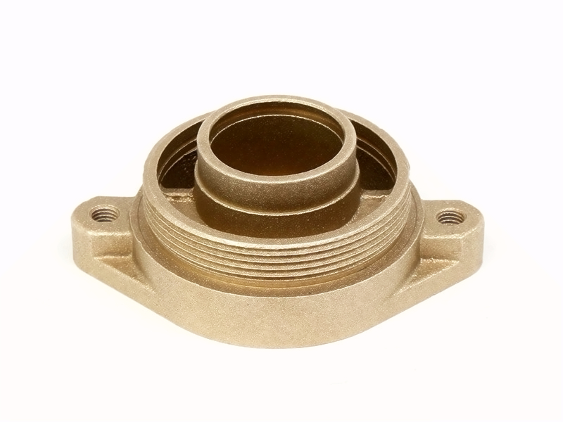
Table of Contents
Define fluid, pressure, temperature and jurisdiction
Confirm the exact alloy and product form
Treat corrosion as several different failure modes
Separate potable-water health from corrosion resistance
Design a sound pressure boundary
Place gates, cores and machining stock around critical zones
Machine threads and seals as a system
Select seals for fluid and temperature
Review flow path, water hammer and drainage
Choose finishes by wetted and exterior function
Clean, assemble and package for fluid service
Build a leak and pressure test strategy
Connect qualification tests to production screening
Validate corrosion, pressure and installation together
Control material, process and change
Compare casting with forging and machining
Compare cost and liability at the accepted fitting
Prepare a decision-ready plumbing RFQ
FAQs

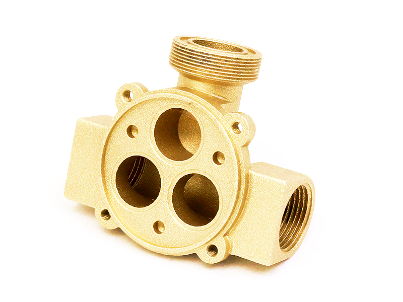
Custom cast brass plumbing fittings with threaded and sealing features

Custom brass casting can be a viable route for corrosion-resistant plumbing fittings when the exact copper-zinc alloy and product form suit the casting process, fluid chemistry, pressure boundary, machining and regulatory scope. Brass is not corrosion-proof, and a familiar alloy name does not guarantee potable-water approval or pressure performance. Dezincification, stress-corrosion cracking, erosion, galvanic contact, casting discontinuities and seal geometry must be addressed for the specific fitting.

A credible supplier therefore quotes a finished and qualified fitting, not a generic brass casting. The scope should identify the material specification, manufacturing route, machined threads and seats, seals, coating, cleaning, pressure or leakage tests, potable-water obligations, traceability and change control. If a casting route cannot provide the required pressure-boundary evidence, forging, hot pressing, machining or another recognized route may be the better choice.

Define fluid, pressure, temperature and jurisdiction

State whether the fitting handles drinking water, nonpotable water, glycol, air, fuel, gas, refrigerant, steam or a process chemical. Include composition, pH or treatment chemicals where known, chlorides, disinfectants, dissolved gases, flow velocity, stagnation, temperature, normal and transient pressure, vacuum, cycling and external environment. A brass that behaves acceptably in one water system may dezincify or crack in another.

Identify the product category and destination market before selecting material. Drinking-water health requirements, plumbing code, gas approval, pressure classification and customer specifications can apply to different scopes. The responsible product owner or certification body must confirm which rules govern the finished fitting. Material chemistry, test reports and supplier declarations are inputs; they do not independently certify the product.

Confirm the exact alloy and product form

Brass designations are not interchangeable, and many are associated with specific wrought, forged or casting product forms. Verify the recognized composition and material standard, then confirm the actual casting process proposed for the geometry. Do not assume that a free-machining rod brass, naval brass sheet/plate grade or another catalog designation can be pressure die cast with its published properties.

Ask for the chemistry range, lead and other restricted constituents, ingot or feedstock control, casting route, heat treatment if any, and route-specific mechanical and corrosion evidence. The broad copper and brass casting scope can begin supplier screening, but qualification must use the exact alloy/product-form combination intended for the fitting.

Treat corrosion as several different failure modes

Uniform tarnish, dezincification, stress-corrosion cracking, pitting, erosion-corrosion and galvanic attack are different mechanisms. Dezincification selectively removes zinc and can leave a porous copper-rich structure with reduced strength and sealing integrity. Stress-corrosion cracking requires a susceptible material, tensile stress and a harmful environment; residual casting/machining stress and installation load can matter. High flow or particles can erode local turns and valve seats.

Dissimilar-metal contact changes the electrochemical system. A brass fitting joined to steel, stainless steel, aluminum or another copper alloy can behave differently depending on area ratio, electrolyte and isolation. Coatings may delay exposure but can create small anodic areas at damage sites. Diagnose the credible mechanism before selecting a so-called corrosion-resistant grade.

Risk

Project inputs

Useful evidence

Dezincification

Alloy chemistry, water composition, temperature, stagnation and disinfectants

Applicable material qualification and test on the exact route/condition, plus section review when required

Stress-corrosion cracking

Residual stress, thread/assembly stress, ammonia or other environment and temperature

Process stress control, representative loading and environment-specific evaluation

Erosion or impingement

Flow rate, particles, local velocity and abrupt turns

Flow/geometry review and service-representative durability testing

Galvanic attack

Mating metals, area ratio, electrolyte and electrical continuity

Assembly-level compatibility review, isolation design and environmental test

Coating breakdown

Layer stack, pores, edges, installation damage and cleaning

Adhesion/porosity inspection and conditioned fitting tests, not finish name alone

Separate potable-water health from corrosion resistance

A corrosion-resistant fitting is not automatically acceptable for drinking water. Health-effects certification can address substances extracted from a complete component under defined conditions. Lead-content rules can be a separate requirement, often calculated across wetted surfaces or product composition according to the applicable jurisdiction. Dezincification resistance and pressure integrity are additional issues again.

The certification scope may include the exact product family, sizes, wetted materials, seals, lubricants, coatings, manufacturing location and quality controls. A supplier cannot transfer approval from a raw alloy, similar valve or different factory without confirmation from the scheme owner. For a potable-water project, obtain the current listing or certificate and verify that the ordered configuration is covered.

Design a sound pressure boundary

Map the wetted wall, pressure thrust, threaded engagement, seat loads, wrench flats and mounting reactions. Keep adequate section at bore intersections, thread roots, grooves and cored passages. Blend abrupt transitions and avoid isolated heavy masses where they create solidification risk next to a thin pressure wall. Include misuse such as over-torque, water hammer, freezing or installation bending when relevant.

The part's nominal pressure class cannot be inferred from alloy strength alone. Geometry, casting quality, temperature, cyclic duty, thread and seal design, corrosion allowance, product standard and safety factor all contribute. If the product requires design qualification, proof, burst, impulse or fatigue testing, the product owner must define the method and acceptance.

Place gates, cores and machining stock around critical zones

Tool design should protect sealing faces, thread regions and bore intersections. Gates, runners, vents, overflows, slides and cores influence fill, oxide formation, shrinkage and local discontinuities. Keep ejector and parting-line effects away from seals where possible. Internal passages need enough access for core control, cleaning and inspection.

A global porosity percentage is not a useful pressure-boundary acceptance rule. Defect size, connection, location and orientation determine consequence. A discontinuity opened by machining across an O-ring land or tapered thread can create a leak path; a small isolated pore in an unloaded exterior boss may have another disposition. Mark critical zones and agree on sectioning, radiography, CT, leak testing or another suitable method according to risk.

Machine threads and seals as a system

Pipe threads, straight threads, O-ring grooves, flare seats, compression cones and gasket faces use different sealing mechanisms. Specify the exact thread standard, class or gauge, truncation, taper where applicable, engagement and sealant assumptions. Parallel threads generally need a separate seal; a thread designation alone does not define the complete joint.

Use post-machining where threads, seats, grooves or datums require it. Fixture from functional datums so sealing features align with the port and mounting interface. Control tool wear, burrs, chips and cleaning. Surface texture, form, waviness and damage limits should be selected for the actual elastomer, gasket or metal seal rather than copied as a universal roughness number.

Select seals for fluid and temperature

Elastomer compatibility depends on fluid, disinfectants, temperature, pressure, compression, movement and expected life. O-ring material, size, squeeze, stretch, gland fill, extrusion gap and installation lead-in belong on the controlled design. A chemically compatible elastomer can still leak if the groove cuts it or if casting/machining variation produces the wrong compression.

For metal seats, compression fittings, tapes or sealants, define installation method and mating component. Lubricants and thread sealants used in drinking-water service may also need approval. Validate the complete joint after assembly torque and environmental conditioning, not just the loose fitting.

Review flow path, water hammer and drainage

A fitting can be pressure-tight yet perform poorly in the system. Abrupt area changes, sharp internal turns, core mismatch and partial blockage increase pressure loss and local velocity. High velocity at a branch, seat or thin wall can accelerate erosion and noise. Dead legs can retain stagnant water or cleaning chemistry. If freezing is credible, trapped water and local restraint can load the pressure wall beyond normal operating conditions.

Review the as-cast and machined flow path, not just nominal port diameters. Include core shift, flash, burrs and coating or scale buildup in the minimum-flow-area analysis. For a valve body, connect seat geometry, travel and pressure drop to the casting datums. For a manifold, examine distribution among branches. Flow testing or simulation should use the actual fluid properties and operating range when hydraulic performance is a controlled requirement.

Pressure transients deserve separate treatment. Rapid valve closure, pump starts, check-valve action and long pipe runs can create water hammer above steady pressure. Define the credible transient and how the installed pipework constrains the fitting. A proof test at one static pressure does not by itself establish impulse life. Where pressure cycling governs, use production-equivalent fittings, seals and mating joints under the agreed waveform and temperature.

Choose finishes by wetted and exterior function

Polishing, nickel/chrome decorative plating, tin or other functional plating, paint, powder coating and passivation or anti-tarnish treatments may be considered according to the substrate and use. Separate wetted surfaces from decorative exterior faces, threads, grounding contacts and seal lands. A decorative finish can improve appearance while introducing pores, dimensional buildup or substances that are not permitted in the wetted path.

Specify substrate preparation, underlayer, final layer, thickness by zone, masking, rack points, adhesion, porosity, chemical resistance and appearance limits. A coating does not repair a porous pressure wall or make an unsuitable base alloy resistant to dezincification. The post-processing scope is a sourcing starting point; exact layers require project qualification.

Clean, assemble and package for fluid service

Machining chips, abrasive residue, plating chemistry, oil and loose debris can damage seals, contaminate water or block small passages. Define cleaning method, rinse quality, drying, cleanliness acceptance and protection before assembly. For potable-water products, process chemicals and lubricants may be part of certification review.

During seal and valve assembly, control component identity, orientation, lubrication, insertion force and torque. Protect seats and threads with caps or suitable packaging. Packaging should prevent corrosion during storage without leaving an unapproved residue inside the fluid path.

Build a leak and pressure test strategy

Choose the test from failure consequence and applicable product requirement. Air-under-water, pressure-decay, mass-flow, tracer-gas, hydrostatic proof, burst and impulse tests answer different questions. Gas tests can be sensitive but require safe fixtures and correlation to the actual fluid; hydrostatic testing limits stored energy but needs drying and contamination control. Define medium, pressure, stabilization, duration, temperature, permissible leakage and calibration.

Design qualification and production screening are not automatically the same. A burst or cyclic qualification may be destructive, while a production leak test protects each pressure boundary when required. Sampling versus 100 percent testing must follow product risk, process evidence and customer or certification rules. Never advertise 100 percent pressure testing unless the quoted control plan actually defines and records it.

Connect qualification tests to production screening

Build a matrix showing what each test proves. Material chemistry identifies the alloy but does not find a connected leak path. Internal imaging can locate selected discontinuities but may not establish leakage at the required threshold. Proof testing demonstrates survival under a defined condition; it is not a burst margin unless the method says so. A sensitive production leak test can detect through-paths but does not prove corrosion resistance or long-term pressure cycling.

Use development samples to correlate internal-quality observations, machining exposure and leakage. This helps define which tool/process controls prevent defects and which final screen catches escapes. Establish reference leaks or calibrated masters where the test method requires them. Control fixture seals and volume so the test measures the fitting rather than a changing fixture. Record part identity, cavity, pressure, time, result and equipment status at the level required by the control plan.

After tool repair, core replacement, material change or a shift in leak-test trend, reopen the correlation rather than assuming prior evidence still applies. The reaction plan should cover containment, retest, sectioning or process review and disposition authority. Qualification and screening work together only when the failure mechanism, detection limit and traceability are explicit.

Validate corrosion, pressure and installation together

Initial leak performance does not prove aged durability. Use representative water or fluid, temperature cycling, pressure cycling, disinfectant exposure, external condensation, salt environment, dezincification or stress-corrosion evaluation as applicable. Include assembled threads, seals, coatings and mating materials. Retest leakage, torque retention and dimensions after conditioning.

Installation can introduce the highest local stress. Test wrench torque, misalignment, pipe loads and repeated service where relevant. Inspect thread roots, bore intersections, sealing lands and coating damage. A fitting that passes a bench pressure test before installation can fail if over-torque or joint stress opens a latent defect.

Control material, process and change

Trace alloy chemistry and heat or batch, casting route, cavity, process revision, machining fixture and tool, finish lot, seal batch and test record. Define characteristics created at each stage and reactions to drift. Material analysis does not replace leak testing; leak testing does not prove dezincification resistance; visual plating inspection does not prove drinking-water suitability.

Changes to alloy source, recycled content policy, melt practice, tool repair, machining, coating chemistry, seal supplier, lubricant or manufacturing site can affect approval. Establish notification and revalidation rules before production. Maintain records at the fitting or lot level required by the product and certification program.

Compare casting with forging and machining

Casting can integrate complex branches, bosses and mounting geometry. Forging or hot pressing may provide a different grain flow and pressure-boundary route. Machining from bar can suit lower volume or simple fittings but creates material waste. Fabricated or hybrid assemblies introduce joints. Compare routes against material availability, geometry, pressure evidence, potable-water scope, machining, yield, tooling and volume.

The finished-cost comparison in copper and brass part costing should include qualification, leak screening, cleaning, coatings, seals and rejected pressure boundaries. Lowest raw casting price is not the lowest accepted fitting cost.

Compare cost and liability at the accepted fitting

Request separate prices for tooling, casting, machining, coating, seals, assembly, inspection, leak testing, documentation and packaging. State whether destructive qualification samples, certification work, retained samples and periodic surveillance are included. A route with inexpensive raw castings can lose its advantage if machining exposes frequent leak paths or if a high-value coating is applied before defective pressure boundaries are screened.

Sequence operations by risk and value. An early leak screen may prevent spending on a fitting that will be rejected later, but the screen must correlate with the final machined boundary. Some defects appear only after threads or seal lands are cut, so a second test stage may be justified. The coordinated casting and machining plan should identify when pressure integrity is checked and who owns scrap created or revealed at each stage.

Include field consequence in supplier comparison. A leaking decorative faucet body, a buried water fitting, a gas component and a chemical manifold do not carry the same containment, recall or documentation risk. Define warranty evidence, nonconformance reporting, traceability retention and change notification in the purchase agreement. Commercial clarity does not replace engineering qualification, but it prevents an apparently low unit price from shifting unpriced failure risk to the buyer.

Prepare a decision-ready plumbing RFQ

Provide CAD and controlled drawings, material and allowed alternatives, manufacturing-route restrictions, fluid chemistry, temperature and pressure profiles, product category, destination market, potable-water or gas scope, mating threads, seals, installation torque, coating, cleaning, annual/release volume, design tests, production tests, traceability and packaging.

Ask the supplier to return exact chemistry/product form, route evidence, corrosion assumptions, pressure-boundary DFM, gate/core/vent plan, critical internal-quality zones, machining and gauge plan, finish stack, seal and assembly scope, certification responsibilities, test methods, control plan, sub-tier ownership, change rules, cost and alternatives. Use project contact only with this qualification package.

A custom cast brass plumbing fitting is corrosion-resistant and reliable only under its defined fluid, stress, temperature, pressure, sealing and regulatory conditions. The defensible purchase is an exact material-route-product combination supported by leak, pressure, corrosion and certification evidence, not a broad promise attached to the word brass.

FAQs

  1. What brass alloys are most corrosion-resistant for plumbing fittings?

  2. Can die cast brass components be certified for drinking water use?

  3. How precise are threads and seals in cast brass pipe fittings?

  4. What post-processing options are available for aesthetic or functional coatings?

  5. What is the lead time for tooling and sampling new brass fittings?

Copyright © 2026 Diecast Precision Works Ltd.All Rights Reserved.