
English

Reliable Brass Die Casting Valve Body Hardware Manufacturing Service
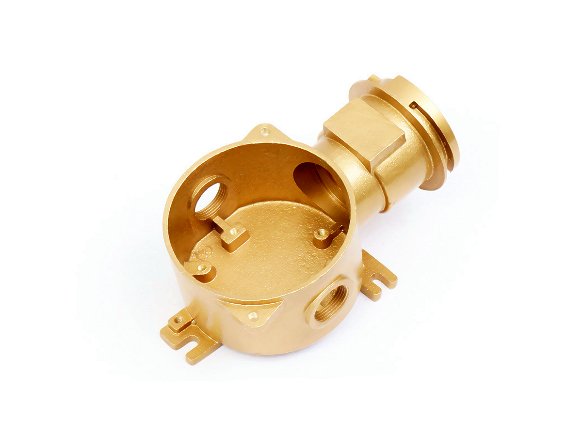
Table of Contents
Define the valve function and failure consequence
Separate valve architectures
Verify alloy designation and casting product form
Treat potable water as a product compliance scope
Map the pressure boundary
Design flow passages with core and cleaning access
Build functional datums from the seat and stem
Specify threads by sealing principle
Control valve-seat geometry and surface
Design stem, bonnet and actuator interfaces
Control flow direction, orientation and stops
Plan casting quality by functional zone
Choose finishing by wetted and external duty
Validate in a sequence that finds the cause
Control cleanliness and foreign material
Prototype the highest-risk interface
Release production with cavity and operation traceability
Plan field identification and failure analysis
Compare finished valve cost and risk
What to send in the valve-body RFQ
The valve-body sourcing decision
FAQs

Cast brass valve body with threaded ports and machined sealing interfaces

A cast brass valve body is reliable when its exact alloy and casting route produce an inspectable pressure boundary, stable flow passages and enough machining stock for seats, stem guides, bonnet joints and ports, and when the assembled valve passes shell, seat-leakage and operating tests for its actual fluid and pressure-temperature envelope. Brass is not automatically suitable because the part resembles a plumbing fitting.

The manufacturing decision starts with valve architecture and sealing principle. Ball, plug, gate, globe, needle, check, mixing and pressure-control valves load the body differently. Closing differential pressure, actuator torque, stem side load, piping load, thermal expansion, corrosion and assembly tolerances can control reliability. A generic pressure rating or thread tolerance cannot replace those inputs.

Define the valve function and failure consequence

State whether the valve isolates, throttles, mixes, diverts, checks flow, regulates pressure or protects against backflow. Define normal and maximum differential pressure in both directions, shell pressure, vacuum, surge, temperature transients, cycling and fire or freeze conditions if relevant. Include whether leakage is a nuisance, contamination risk, energy loss or safety hazard.

Specify allowed seat leakage by procedure and test condition rather than saying bubble-tight. Metal seats, elastomer seats and PTFE-family seats behave differently across pressure, temperature and cycling. Shell leakage, external stem leakage and through-seat leakage are separate acceptance questions. The valve owner should identify each boundary.

Separate valve architectures

Valve type

Body features that control

Primary manufacturing risk

Assembly evidence

Ball or plug valve

Seat pockets, ball/plug bore, stem axis and body/connector joint

Seat coaxiality, cavity finish, torque and trapped pressure

Shell/seat leakage, operating torque and cycling

Gate or globe valve

Seat rings/faces, guide, stem/bonnet axis and body cavity

Seat alignment, guide distortion and inaccessible casting zones

Seat contact/leakage, stem travel and pressure operation

Check valve

Seat, hinge/guide, stop and flow recovery

Closing alignment, chatter, impact and debris traps

Cracking/closing behavior, leakage and endurance

Mixing/control valve

Multiple ports, metering windows, cartridge bore and actuator interface

Core shift, port timing, dead zones and stem side load

Flow characteristic, shutoff, torque and control repeatability

Pressure regulator/backflow body

Diaphragm/piston chambers, seats, vents and cover joint

Functional-area relationship and cross-leakage

Set pressure, flow, leakage and fault-condition test

These distinctions affect the feasibility of brass casting. A simple two-port body may be accessible to slides and machining; an internal S-shaped passage or enclosed seat cage may require cores, a split body, inserts or another casting method. Choose the route after the pressure and flow architecture are stable.

Verify alloy designation and casting product form

Brass 360, CuZn37, naval brass and other familiar names are often associated with bar, tube, plate, forging or other product forms. Their published strength, machinability and corrosion behavior do not automatically apply to a pressure-die-cast body. Ask for the exact material standard, designation, chemistry, feedstock, casting process and final condition.

Silicon brass C87850 or another qualified casting alloy may be considered, but geometry, wall transitions, hot tearing, porosity and machining response still need proof. A page describing copper and brass alloys is not a purchase specification. Material alternatives should identify how pressure integrity, dezincification, restricted substances and machining change.

Treat potable water as a product compliance scope

Potable-water suitability is not established by calling an alloy low lead or lead free. The target market may regulate weighted lead content, extractables, dezincification or complete-product sanitation. Identify the law, certification scheme, standard edition, component scope, wetted surface area and assembly materials. An alloy chemistry certificate addresses only part of that package.

Machining, plating, lubricants, seals, assembly aids and cleaning can change the wetted system. Certification may apply to a specific valve model, size, production site and material formulation. Request current evidence from the responsible certifying body and define change notification. Do not state automatic NSF, WRAS or other approval from an alloy name.

Map the pressure boundary

Mark every wall between process fluid and atmosphere, another port, actuator cavity or noncompatible fluid. Include threaded ends, body connectors, bonnet joints, plugs, stem packing, seat pockets and drilled intersections. Distinguish normal pressure, shutoff differential, proof, surge, vacuum and any trapped-cavity pressure.

Use the governing valve/piping design method to establish allowable stress, wall and reinforcement for material, temperature and corrosion allowance. Casting draft and nominal wall are not pressure design. Include external piping forces, wrench torque, actuator reaction, mounting loads and thermal gradients. A valve can pass static pressure and crack during installation or cycling.

Design flow passages with core and cleaning access

Port area, turns, seat throat and cavity shape affect pressure drop, flow coefficient, cavitation, noise and solids retention. Throttling valves need special attention to vena contracta, jet impingement and erosion. On-off valves still need smooth transitions and drainage. Flow performance should be evaluated with the closing member and trim installed.

Core shift, internal flash, gate remnants and machining burrs can restrict a passage or damage a seat. Define how passages are created, inspected and cleaned. For intersecting drilled ports, control burr removal and plug joints. If internal geometry cannot be measured directly, use sections, imaging, flow checks or other evidence tied to the critical question.

Build functional datums from the seat and stem

The correct datum system depends on closure. A ball valve may need the stem axis related to seat pockets and connector axis. A globe valve needs seat and stem/guide alignment. A cartridge valve needs bore form, depth and port timing. A check valve needs seat, guide or hinge alignment. These relationships matter more than a convenient cast outside surface.

Plan machining from stable pads or pre-machined datums so the seat, stem bore, bonnet joint and ports remain related. Multi-setup post-machining needs a documented datum-transfer strategy. Excess stock can expose subsurface defects or increase distortion; insufficient stock can leave interrupted sealing surfaces.

Specify threads by sealing principle

Tapered pipe threads seal through flank interference plus an approved sealant; parallel threads often rely on an O-ring, bonded seal or gasket; bonnet threads carry load and establish compression; stem threads convert torque to travel. Name the standard, size, class/tolerance, gauging method, engagement and seal system. A plus/minus pitch-diameter number is not a complete thread requirement.

Thread quality includes form, taper where applicable, truncation, lead, burrs, cleanliness and relation to port axis or sealing face. Coating changes gauge response and fit. Define whether gauging occurs before or after finish and how sealant affects assembly torque. Sample versus full gauging should follow risk and demonstrated process capability, not an automatic promise.

Control valve-seat geometry and surface

Seat sealing depends on geometry, material pair, contact stress, surface topography, cleanliness and deformation under pressure/temperature. Elastomer and polymer seats need controlled glands and support; metal seats need alignment and contact pattern. Roughness alone cannot predict leakage, and excessive polishing can change shape or retain contamination differently.

Define seat diameter/form, angle or pocket, runout/coaxiality, surface method and damage limits. Protect seats during deburring, plating and assembly. A scratch across the sealing path differs from a mark outside it. Verify the assembled seat under differential pressure in required directions and temperatures.

Design stem, bonnet and actuator interfaces

Stem bore and guide alignment influence packing wear, operating torque and closing-element alignment. The bonnet joint must carry pressure separation and mechanical loads while maintaining gasket or O-ring compression. Actuators add torque, thrust, side load and stop reactions. Define maximum actuator output and fault/stall behavior, not only normal valve torque.

Packing gland threads, stem seals and bearing surfaces require surface and material compatibility. Thermal cycles can relax compression or increase friction. Test operating torque and external leakage over representative cycles. The bare body cannot prove stem-seal life.

Control flow direction, orientation and stops

Some valves are bidirectional; others have a preferred pressure direction because seat support, check-element motion, regulator sensing or body-cavity relief changes with flow. Mark inlet, outlet, high-pressure side and allowed installation orientation on controlled drawings and the product where required. A symmetric external body can hide an asymmetric internal trim.

Ball and plug valves may trap fluid in a closed cavity. Thermal expansion or freezing can create pressure not shown by line pressure alone. Define cavity relief, venting and double-block behavior. Check valves need gravity, spring and flow direction considered together; a vertical installation can behave differently from a horizontal test fixture.

Actuator and manual stops should prevent the closing element from overtraveling into seats or body features. Stop torque and impact pass through the stem boss and mounting pattern. Validate indication and fail position after assembly. Casting marks, machining orientation and assembly fixtures should prevent wrong-hand bodies or misclocked trim from reaching the test line.

Plan casting quality by functional zone

Identify seat, stem, bonnet, threaded-port and thin-wall junctions as separate quality zones. Pores in a cosmetic boss differ from shrinkage opened by seat machining or a connected path across the shell. Do not use one total porosity percentage as a universal acceptance rule.

Choose radiography, CT, penetrant, sections, machining trials or pressure/leak tests according to defect type and resolution. Available inspection equipment should answer a stated question. Correlate indications with finished-body and valve tests before setting production limits.

Choose finishing by wetted and external duty

Bare brass, nickel systems, decorative chrome, organic barriers or localized surface processing can be considered, but wetted and external zones have different needs. A decorative exterior finish does not qualify a wetted chemical surface. A coating in seat pockets, threads or cartridge bores changes fit and sealing. Define masking and buildup before machining release.

Surface preparation, adhesion, pores, edge coverage and repair govern performance. Test the finished valve in the actual fluid and thermal cycle. Salt spray can screen exterior coating consistency but does not reproduce pressurized immersion, flow, dezincification, stress corrosion or seal interaction.

Validate in a sequence that finds the cause

Test level

Question answered

Conditions to define

Limitation

Material/corrosion specimen

Does the alloy/finish resist a defined mechanism?

Fluid, chemistry, temperature, stress, velocity and time

Does not prove body pressure or valve sealing

Finished body shell test

Does the pressure boundary leak or deform?

Medium, pressure, temperature, dwell, sensitivity and fixture

Does not prove seat or stem leakage

Assembled seat-leakage test

Does the closing system meet shutoff criteria?

Differential, direction, medium, temperature and class/limit

One cycle does not prove durability

Operating/torque test

Does the valve move and close without binding?

Pressure, temperature, actuator, speed and lubrication

No-flow cycling may miss hydraulic force/noise

Flow/cycle/environment test

Does performance survive service exposure?

Fluid, flow, thermal/pressure cycles, contamination and acceptance

Must represent production material and assembly

Use an applicable valve standard or customer procedure only after scope and edition are confirmed. A pressure-test standard does not necessarily define design suitability or drinking-water compliance. Record instruments, sensitivity, stabilization and allowed leakage. Trace test results to body material, tool cavity, machining and assembly.

Control cleanliness and foreign material

Core residue, chips, thread burrs, blasting media, plating debris and cleaning chemicals can score seats, jam a check element or contaminate potable and process fluid. Define which passages are flushed, brushed, ultrasonically cleaned or otherwise processed. Blind cavities behind seats, plugs and regulator diaphragms deserve explicit access.

Set cleanliness acceptance according to valve size and service. Visual inspection may be enough for a coarse utility valve; a cartridge, oxygen-sensitive or sanitary application may require controlled particle/residue methods. Drying matters because retained rinse water can corrode, freeze or interfere with lubricant and seals. Cap ports and package the cleaned valve to preserve condition.

Pressure-test media and corrosion inhibitors must also be compatible and removable where necessary. If the same fixture tests different fluids or valve families, control cross-contamination. A valve that passes leakage with debris temporarily embedded in a soft seat may fail after the first operation, so cycle the closing member as required before final acceptance.

Prototype the highest-risk interface

A machined prototype can establish envelope, porting, seat, stem and assembly fit while leaving casting integrity and production stock unresolved. A temporary-route casting can explore geometry but may not reproduce die filling or cavity variation. Production-intent bodies are needed before pressure and leakage approval transfers to mass production.

Define what each prototype closes. Flow characterization may need complete trim. Seat leakage needs production seals and finish. Chemical testing needs the intended alloy and wetted surface. The logic of functional prototype testing prevents a successful fit sample from being treated as a qualified valve.

Release production with cavity and operation traceability

Trace alloy lot, melt/process record, tool/cavity, trim, machining setup, cutter/gauge, finish batch, assembly components and test result. Multi-cavity bodies need cavity-specific evidence for core position, stock, leakage and flow-sensitive geometry. Pool data only after equivalence is demonstrated.

Monitor critical seat/stem/bonnet relationships, thread gauge results, shell-test rejects, seat leakage and operating torque. Define containment and reaction when trends move. Before mass production, show throughput through machining, washing, finishing, assembly and testing, not only casting cycle.

Plan field identification and failure analysis

Mark model, flow direction, pressure/temperature designation and trace code according to product and regulatory needs without weakening the pressure wall. Preserve the relationship among finished valve, body cavity, material lot, trim revision and test record. Permanent markings must remain readable after finish and service, while labels should not obstruct inspection or wrench zones.

For a field return, record installed orientation, fluid history, pressure/temperature events, actuator settings, maintenance and leakage location before disassembly. Distinguish shell leakage, body-joint leakage, stem leakage and through-seat leakage. Photograph deposits and fracture or corrosion surfaces before cleaning. An apparently leaking body may actually have damaged packing, a scratched seat or incorrect connector sealant.

Compare the returned part with production dimensions, internal inspection and sister-cavity data. Section only after non-destructive evidence is preserved. Feed a confirmed cause into material, tool, machining, finish, assembly or service controls. Replacing an alloy or adding a coating without identifying pressure, chemistry, stress and defect location can introduce a new failure mode.

Compare finished valve cost and risk

Include alloy, tooling/slides/cores, machining, deburring, washing, finish, seals/trim, assembly, shell/seat tests and scrap after value-added work. Compare casting with forging, hot pressing, machining from bar and other valve materials under the same pressure, fluid and volume. Die casting may integrate complex ports, but a mostly machined pressure body may favor another route.

Count pressure drop, actuator size/energy, leakage consequence, maintenance and certification changes. A cheap body that increases operating torque or fails extraction tests has poor total value. A premium alloy is justified only when its cast form and service evidence solve a real corrosion or mechanical risk.

What to send in the valve-body RFQ

Send controlled CAD/drawings, valve type/function, port and flow data, trim/seat/stem/bonnet/actuator interfaces, pressure-temperature envelope, shutoff differential/directions, vacuum/surge, piping loads, cycles, operating torque and leakage limits. Provide fluid chemistry, contamination, cleaning, environment and failure consequence.

Name exact alloy standard/product form or allow documented alternatives. Mark pressure zones, cast/machined surfaces, functional datums, threads, seats, finish/masking and cleanliness. State prototype/annual quantity, applicable standards/editions, shell/seat/flow/cycle/corrosion tests, sampling, traceability, documentation and change control. Request separate raw-body, machining, finishing, assembly and test costs/schedules.

The valve-body sourcing decision

Choose brass die casting for a valve body when an exact cast alloy and feasible core/slide strategy produce the required pressure and flow geometry, machining establishes seat/stem/bonnet/port relationships, and the assembled valve passes fluid-specific shell, leakage and operating tests. Reject proposals based on fixed PN, temperature, tolerance or compliance claims detached from the valve design.

A reliable release connects material/product form, pressure-boundary DFM, functional machining datums, qualified assembly and valve-level evidence. That chain is what makes cast hardware a controllable fluid valve rather than merely a threaded brass body.

FAQs

  1. What brass alloy is best suited for potable water valve bodies?

  2. How accurate are the thread and bore tolerances in cast brass valves?

  3. Can brass valve bodies handle chemical or high-temperature fluids?

  4. What is the lead time for prototype and full-scale valve casting?

  5. What finishing options improve brass corrosion resistance in valve applications?
Copyright © 2026 Diecast Precision Works Ltd.All Rights Reserved.


