Steel Investment Casting: Bracket Strength, Datum, Blasting
A 45 steel bracket holds a 355 MPa yield because the 25–30 mm boss is fed, the quench and temper window is held, and a test bar is poured with the part. The mounting face is a separate problem: hole pitch within ±0.2 mm and a face flat to 0.1 mm survive only when blasting runs before the final cut. Steel investment casting shapes the blank, and the order of the later steps decides whether the drawing is met.
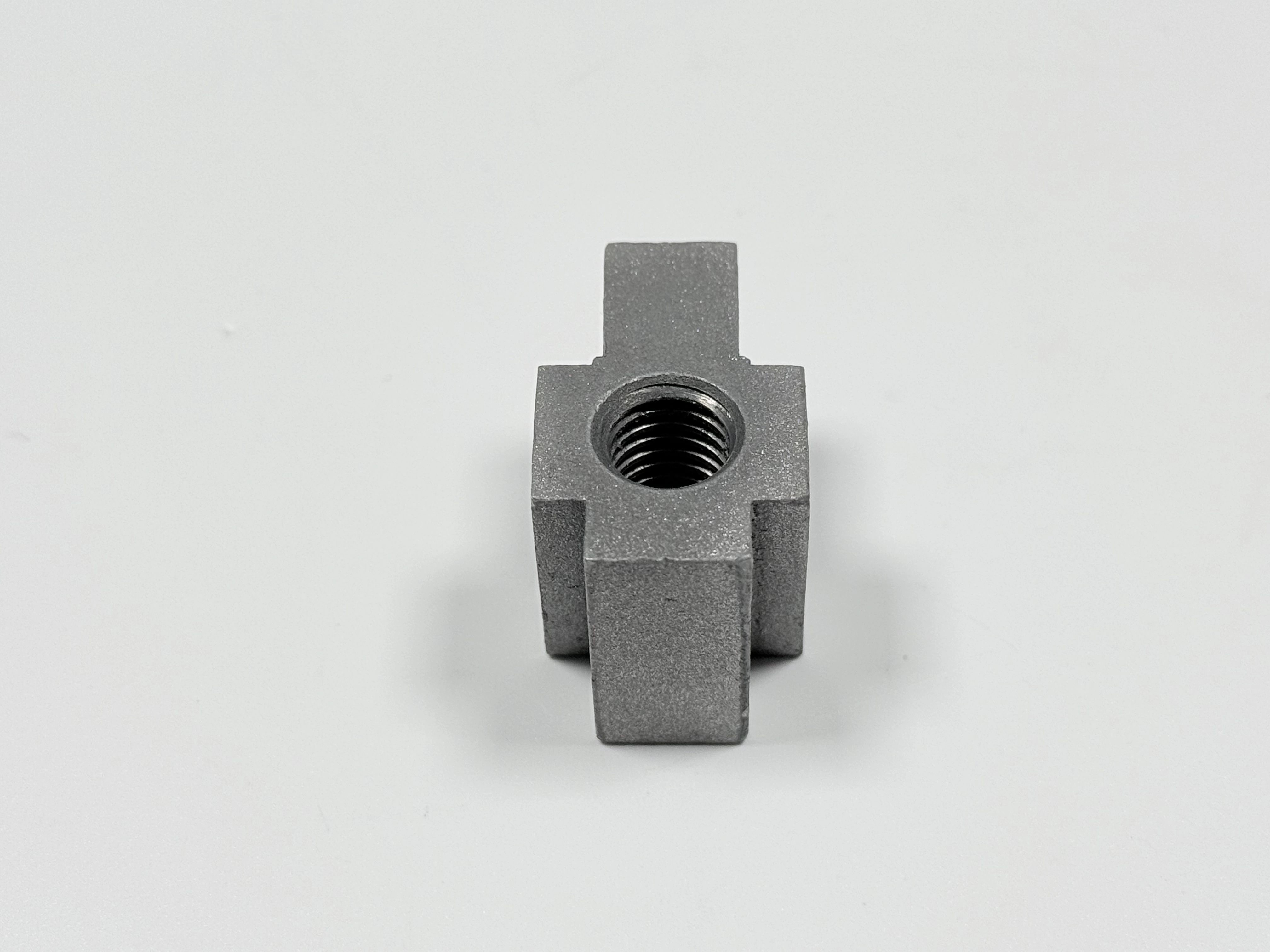
Three Requirements: One Sequence to Hold Them
Three numbers on the drawing belong to three different steps: 355 MPa yield, a hole pattern held to ±0.2 mm, and 0.1 mm of flatness across the mounting face. Casting sets the section, heat treatment sets the strength, and machining sets the other two. Move one step out of order and one number changes while the others hold.
Strength starts at the section. The thick boss freezes last, so a riser has to stay liquid long enough to feed it. Quenching from 840–860 °C then has to carry that section through the transformation range, and tempering at 550–600 °C brings it to HB 220–250. A cast-on bar records what the furnace did to that heat.
Table 1 pairs each requirement with the step that sets it and the check that proves it.
Requirement | Target | Set at | Proved by |
|---|---|---|---|
Yield strength | ≥355 MPa | Riser feed, 840–860 °C quench, 550–600 °C temper | Cast-on bar to ASTM A370 |
Hole pitch | ±0.2 mm | Fixture and program after the face is cut | CMM |
Face flatness | 0.1 mm | Final cut from the machined datum | CMM or surface plate |
Wall and boss | 8–12 mm wall, 25–30 mm boss | Pattern and riser plan | Section check on the blank |
Blast cleanliness | Sa 2.5 (ISO 8501-1) | Blasting before the final cut | Comparator |
What the Drawing Must Fix Before the Pattern
The mounting face is the datum, and the drawing has to name it before the pattern is cut. An as-cast face carries draft, sand texture, and heat-treat distortion, so it cannot sit flat on a frame or serve as a measuring reference. Mark the face that gets cut, the stock left on it, and the tolerances measured from it.
A drawing that names 45 steel and a yield target but leaves the datum to the shop will produce different parts from different suppliers. The datum callout, the stock allowance, and the gauge belong on the same sheet as the hole pattern. Datum strategy for cast and machined parts starts at that sheet.
Sand Molds: 2–4 Parts per Flask
The mold plan calls for a sand mold, a wood or aluminum pattern, and 2–4 parts per flask. That count decides how pattern cost is spread and how many brackets share one pour. A flask of four parts also puts four brackets on the same heat, so the cast-on bar speaks for all of them.
The route name and the mold plan are read together. Where the RFQ says steel investment casting and the plan says sand mold, the shop confirms which route runs before the pattern is cut.
Pattern material and flask count are quoted as one item on the sand casting route.
The 25–30 mm Section: Where 355 MPa Is Decided
The 25–30 mm boss freezes last, and it needs a riser that stays liquid while the section pulls metal inward. Without that feed, shrinkage sits in the boss and the section carries less load than the drawing assumes.
Cooling rate is the second half. A thick section sheds heat slowly at the core, so the center may miss the transformation range in the quench. The 550–600 °C temper then works on a softer structure, and the body lands under 355 MPa while the bar still passes.
Hypothetical Engineering Scenario: a 180×120×60 mm bracket at 1.8–2.5 kg with a 25–30 mm boss. With the riser, body hardness lands in HB 220–250; without it, the bar stays green and the boss does not. The figures are drawing targets, not a batch result.
Thicker is not safer. Every extra millimeter slows the core and asks for a larger riser, so the section is a load decision first.
Quench 840–860 °C, Temper 550–600 °C: One Window
The quench window runs 840–860 °C, hot enough to take carbon into solution without growing the grain. Below it, austenite does not fully form and the temper has less to work with.
Tempering at 550–600 °C pairs with HB 220–250. A temper at the low end leaves hardness above 250 and costs toughness; at the high end, hardness falls below 220 and yield follows it down.
Hardness is the shop-floor proxy. A number inside the HB 220–250 band says the section answered the temper, and it says nothing about the tensile number. The bar still has to be pulled to ASTM A370.
The window assumes a 45 steel heat to GB/T 699-2015 and the sections in the table. Change the grade or the section and the window is set again; casting material selection comes before the heat-treat sheet.
Test Bars: Cast With the Part, Tested to ASTM A370
A cast-on test bar is poured from the same ladle as the bracket and rides the same heat treatment. The pull to ASTM A370 reports yield and tensile strength for that heat.
The bar proves the melt and the furnace. It cannot prove the core of a 25–30 mm boss, because the bar is a smaller section and cools faster. A passing bar and a soft boss can leave the same batch.
The bar's position belongs in the pattern review, where the section it has to represent gets fixed. Mechanical property testing covers the pull and the report behind it.
An example batch record shows the gap: the bar passed, the body did not reach 355 MPa, and the fix was a riser on the thick section plus a temper adjustment. The riser cost less than the rework it prevented.
Hardness HB 220–250: The Body Check and Four Gates
Hardness on the body is the check the bar cannot make. A value inside HB 220–250 says the thick section took the temper; a value outside it says the section or the furnace ran off the window, and the bar may still be green.
Fix the test points on the drawing. One reading on a cleaned pad near the gate is not a body check, because the boss and the 8–12 mm wall cool at different rates. The number that counts comes off the 25–30 mm section.
Four gates hold the part before shipment: strength from the cast-on bar and the body hardness, size from a CMM or a surface plate, blast cleanliness from a comparator, and surface defects from magnetic particle or penetrant inspection. Each gate needs its gauge named on the drawing, or a second inspector cannot repeat the result.
Blasting Sa 2.5: A Size Decision Before Machining
Sa 2.5 to ISO 8501-1 describes how clean the surface is after blast cleaning, not how rough it is. The grade asks for near-white metal with scale and rust removed, judged against a comparator.
The blast removes metal along with scale, which is why it runs before the final cut. Blast a finished face and the cut edges round, the hole edges move, and the pitch has to be measured again. Table 2 sets the two orders side by side.
Order | What it holds | What it costs | Where it fails |
|---|---|---|---|
Blast, then cut the face | Pitch and flatness are cut after the last step that removes metal | One extra setup and masking | Mask damage on a finished hole |
Cut the face, then blast | A clean face before the blast | A second cut on the datum and a re-check of the pitch | Rounded edges and a pitch that moved |
Masking follows the same logic. Any hole or face already cut stays covered through the blast, and the mounting face is cut afterwards, so the blast never touches the datum. The sand blasting step is signed off against a comparator, and the blasting specification for cast parts starts from that grade.
Flatness 0.1: The Machined Datum
Flatness 0.1 mm is cut, not cast. The blank arrives with draft and with heat-treat distortion, and the stock left on the face has to cover both before the final cut cleans up across the whole face.
If the stock runs short, the cutter cleans one corner and the plate rocks on the rest. The reading fails even though the machine held its own tolerance. Figure 2 shows the finished face on a plate, which is the check that matters.
Distortion is the variable that eats the stock. A bracket that warps in the quench can lose most of the allowance before it reaches the mill, so the drawing carries stock for it and the machining of castings plan starts from the blank condition.
A sand hole under the face is the other risk. Cut into one and the face opens, so the blank is checked before the cut and the scrap is caught before the machining hours go in.
Hole Pitch ±0.2: Fixture, Not Hand Drill
Hole pitch ±0.2 mm across the mounting face comes from a fixture and a program. The holes are drilled after the face is cut, from the same datum, so the pitch and the flatness share one reference.
A hand-drilled hole lands where the punch mark sits, and the mark sits where the layout allowed. Across the pattern the error adds up, and the mating frame decides whether the part assembles.
Check the pitch on a CMM with the part clamped as it will be bolted. An unclamped bracket can relax between the machine and the gauge, and the reading moves with it. CNC machining of the face and the holes belongs in one setup for that reason.
If the mating frame carries slotted holes, the pitch can be looser than ±0.2 mm. That is a drawing decision, and it has to be made before the fixture is built.
Passivation: Only If the Drawing Says So
Carbon steel does not passivate like stainless steel. The three words on drawings, passivation, phosphating, and black oxide, name three processes with three acceptance criteria, and a 45 steel bracket usually takes one of the latter two.
The surface callout says passivation pending the customer drawing, and that is the correct state to hold. The last step cannot start until the drawing names one process and one standard; otherwise the shop guesses and the inspection plan has nothing to check against.
Put one word on the purchase order, not three. A PO that says surface treatment leaves the process open, and two batches can arrive with different finishes, both acceptable to the eye and neither matching the drawing.
The surface finishing options do different things to a steel face, and the callout decides which one runs. A metal casting supply case on the same site shows how a finish callout drives a batch record.
FAQ