Machined Mounting Face: Why a Bracket Cannot Be As-Cast
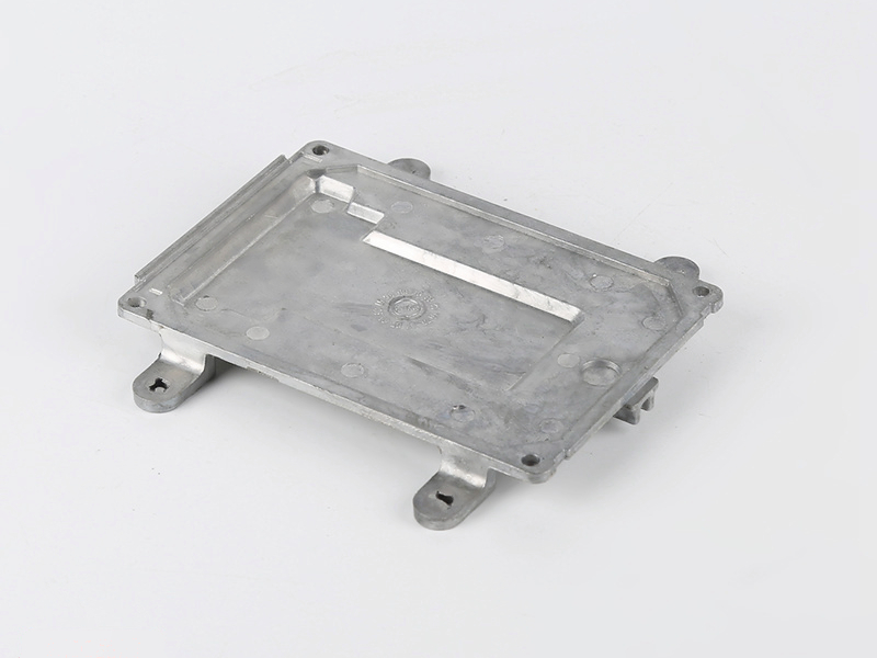
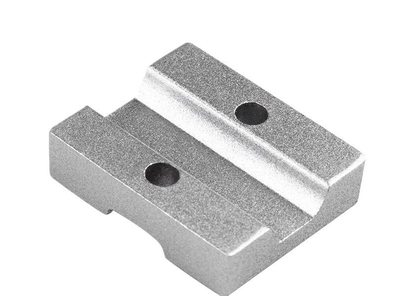
In machined mounting face casting, the face is cut after blasting, not before. An as-cast face is no datum: draft, sand texture and heat-treatment movement all land on it, and none is measured before setup. CNC machining of castings cuts the face and holes from one located surface, which holds ±0.2 mm.
Why an As-Cast Face Cannot Be a Datum
Pattern draft leaves the cast face a slope, not a plane. Sand texture sits on it, and the quench at 840–860 °C and temper at 550–600 °C move the casting again. The drawing then asks for 0.1 mm flatness on the cut face, one part in 250 to 300 of the 25–30 mm section that just came through the quench.
A datum is a surface the next operation can locate from, part after part. An as-cast face differs from casting to casting, so each setup starts somewhere new and every cut inherits the scatter. Set the 45 steel bracket on that face and the bolts pull it down, taking the holes with them.
The exception is a face that carries only a cover or a rubber pad. Once bolts clamp the bracket to a frame, the face is a datum and has to be cut.
Flatness 0.1 and Hole Pitch ±0.2
Flatness and hole pitch are one requirement. A face that is 0.1 mm out does not sit on the frame; the bolts close the gap, and the hole centers shift as the face bends. The pitch then reads wide or narrow depending on how the bracket is clamped.
Put both numbers on one report, in the clamped state. A CMM (coordinate measuring machine) maps the face and the hole centers in one setup. A surface plate with a height gauge finds the rocking corner, enough to reject a bracket, not to release it.
Both values are design targets: 0.1 mm flatness and ±0.2 mm pitch. A face that bends by 0.1 mm can spend half of the ±0.2 mm pitch budget before a hole is drilled. Slotted holes in the frame are the one case that loosens the pitch; without slots it stands.
The Order: Blast, Then Machine
Blasting to Sa 2.5 (ISO 8501-1) removes metal from every exposed surface. Machine the face first and the following blast moves the surface just qualified, taking the hole edges with it. The 0.1 mm flatness and the ±0.2 mm pitch then describe a part that no longer exists.
Blast first, and the cut is the last operation that moves metal. Face and holes come after the surface settles, so the CMM report describes the part that ships. That order costs one more setup; the other costs a rejected batch.
Where a bracket is blasted twice, mask the machined face and the holes. Sa 2.5 does not stop at the edge of a masked area, and an unmasked hole loses its edge. A part with no machined face can be blasted last; this bracket cannot.
Sand Holes and Shrinkage Under the Cut
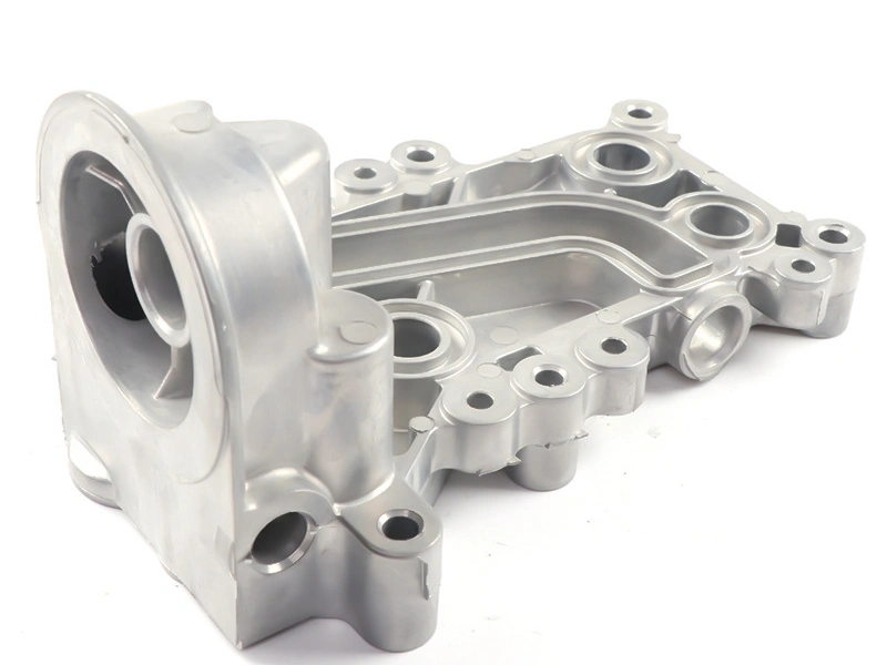
A sand hole or a shrinkage cavity under the mounting face stays hidden until the cutter opens it. The face then has a crater where the bolt seat should be, and 0.1 mm flatness fails at one point. Blending does not repair that, because the seat is gone.
Run magnetic particle or dye penetrant on the face before the cut. Both methods find what reaches the surface. Neither finds a cavity below it, so the check lowers the risk without removing it. The wall is a design target of 8–12 mm, so a cavity that takes half the section leaves little to clamp.
The acceptance rule has to say what happens when the cut opens a cavity: scrap the part, do not fill and re-machine it.
What the Drawing Must Show
Four callouts carry this decision. Mark the mounting face and the datum it is cut from. Put 0.1 mm flatness across the face and ±0.2 mm on the hole pitch. State the cut comes after the blast. Add Sa 2.5 (ISO 8501-1) to the as-blasted surfaces.
Requirement | Value (unit) | Verified by | Order |
|---|---|---|---|
Mounting face | 0.1 mm flatness | CMM or surface plate | Cut after the blast |
Hole pitch | ±0.2 mm | CMM, clamped | Drilled with the face |
Blast | Sa 2.5, ISO 8501-1 | Comparator plate | Before the cut |
Wall | 8–12 mm | Drawing and section | Cast, not cut |
Then ask for the report: CMM readings on the face and hole centers in the clamped state, plus the penetrant record from before the cut. Send the drawing with the datum face marked and the blast callout written out; for that step, see surface preparation.