How Machining of Castings Turns Rough Blanks Into Finished Parts
How Machining of Castings Turns Rough Blanks Into Finished Parts
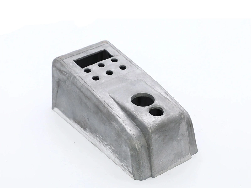
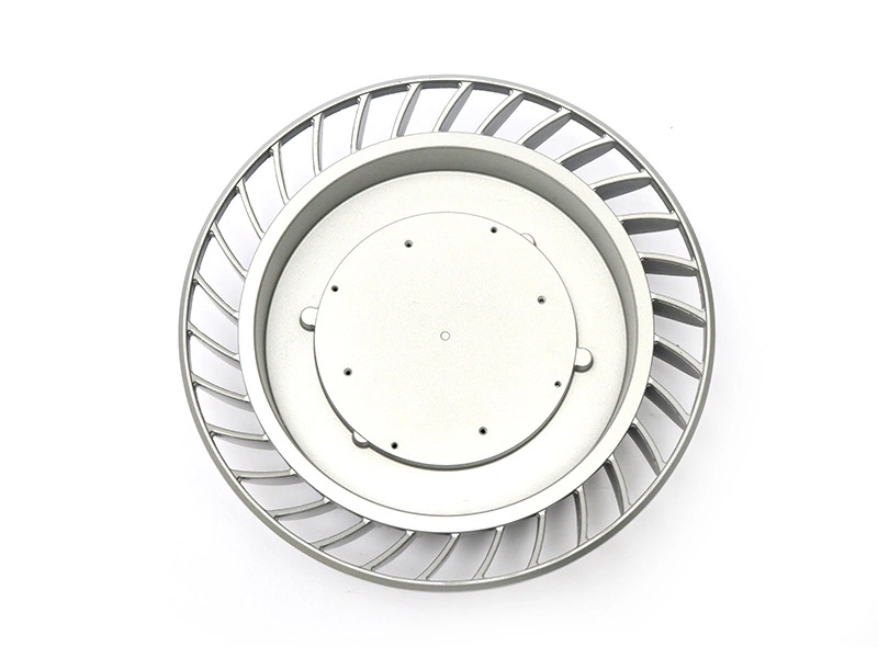
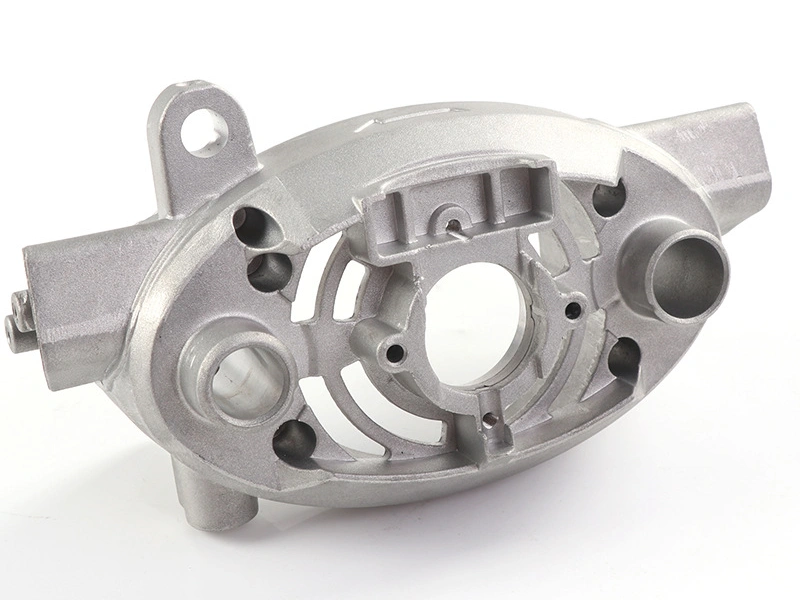
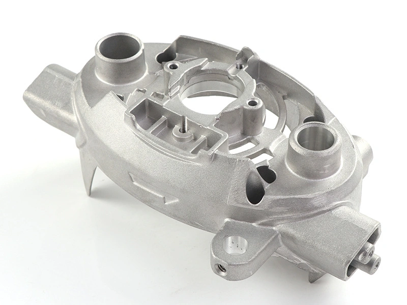
Machining of castings is the controlled CNC finishing work that turns a rough or near-net casting into a functional production part. Casting creates the main shape, wall structure, ribs, bosses, pockets and exterior form. Machining finishes the features that must meet tighter requirements, such as threaded holes, dowel holes, gasket faces, bearing bores, shaft seats, mounting pads and datum surfaces.
Buyers search this term when a casting is close to the required shape but not ready for assembly. The part may fit the envelope, yet still fail if the holes are not positioned correctly, if a sealing face is not flat, if a bearing bore is not round, or if a threaded boss has not been tapped to depth. Machining is the step that converts useful cast geometry into controlled interfaces.
The best result comes from deciding the machining plan before the casting tool or casting batch is released. If the casting does not leave enough stock, CNC machining cannot recover a clean face. If the datum strategy is weak, holes and faces can shift. If finishing is planned after machining without masking, coating may block a thread or change a fit dimension.
What Buyers Mean by Machining of Castings
Buyers usually mean one of three situations. First, they may already have rough castings and need a machining supplier to finish the functional areas. Second, they may be planning new cast parts and want to know which features should be machined after casting. Third, they may be comparing a raw casting quote with a finished machined casting quote.
The keyword is therefore practical and commercial. It is not only about the act of cutting metal. It is about turning the casting into a usable component with controlled dimensions, clean edges, inspected features and surfaces that can survive finishing, assembly and shipment.
For a broader comparison of route selection, CNC machining vs casting helps buyers decide when to form the main shape by casting and when to machine directly from billet.
Buyer Situation | Machining Question | Useful Output |
|---|---|---|
Existing rough casting | Can the blank clean up to the required dimensions? | Machining feasibility review |
New casting design | Which features need machining stock? | Feature map and allowance plan |
Supplier comparison | Does the quote include raw casting only or finished machining? | Finished-part scope check |
Assembly problem | Which face, hole or bore controls the failure? | Datum and inspection review |
Repeat order | Can the machining setup be repeated? | Fixture and inspection record |
Which Casting Features Usually Need Machining?
Features usually need machining when they control contact, fastening, sealing, movement, location or inspection. A cast wall may be acceptable as-cast. A hidden rib may only need flash removal. But a threaded hole, a gasket face or a bearing bore usually needs CNC finishing because the final function depends on accuracy and surface condition.
Common machined features include drilled and tapped holes, reamed dowel holes, milled datum pads, faced gasket surfaces, bored shaft seats, countersunk mounting holes, precision slots and flat mounting surfaces. These features should be identified on the drawing before tooling, because the casting must include enough material for cleanup.
For feature-level planning, design details before machining cast parts explains why drawings should mark the surfaces that truly control function.
Feature | Why It Is Machined | Buyer Check |
|---|---|---|
Threaded boss | Controls fastening depth, pitch and alignment | Boss wall, pilot hole and thread gauge |
Gasket face | Controls sealing and leakage risk | Flatness, roughness and porosity exposure |
Bearing bore | Controls diameter, roundness and shaft fit | Bore tolerance and datum relationship |
Dowel hole | Controls location between mating parts | Hole position and inspection method |
Mounting pad | Controls flat contact and assembly height | Machining stock and surface finish |
Machining Allowance for Castings
Machining allowance is the extra material left on the casting so CNC machining can clean up a face, hole, bore or datum. Allowance must be enough to remove casting variation, surface skin, local distortion and draft effects. It should not be so large that every part needs excessive cutting time or heavy clamping.
For many die cast aluminum or zinc parts, local cleanup stock is often discussed around 0.5 to 2.0 mm on selected machined faces, but the exact value must follow part size, casting process, expected distortion, material, surface condition and tolerance target. Sand castings or large parts may need larger allowances. A sealing face with flatness demand needs a different allowance than a cosmetic trim edge.
The machining allowance question should be settled before tooling because the mold defines where stock exists. Machining allowance before die casting tooling is especially important for gasket faces, bearing bores, threaded bosses and datum pads.
Allowance Area | Planning Logic | Risk if Too Low |
|---|---|---|
Sealing face | Leave stock for flatness and surface cleanup | Leak path, exposed pore or uneven contact |
Bearing bore | Leave stock for boring or reaming | Diameter cannot clean up |
Threaded boss | Plan pilot hole, tapping depth and wall thickness | Weak thread or breakthrough |
Datum pad | Create a reliable reference for later cuts | Unstable feature relationships |
Visible trim edge | Clean flash and control cosmetic transition | Rough edge or finish rejection |
Datum and Fixture Strategy for Machining Castings
Castings are not perfect blocks. They may include draft, parting lines, ejector marks, slight distortion and surface texture. A machining fixture must locate the part repeatably without forcing it into a false shape. If the fixture clamps against an unstable as-cast wall, a hole pattern can shift. If it clamps a thin wall too hard, the part may spring back after machining.
The supplier should define the first machining datum, the secondary supports and the clamping points. If a cast surface becomes a datum, that surface must be reliable enough for the fixture. If a machined datum is created first, later operations should reference that surface. The inspection datum should match the functional requirement, not just the easiest surface to measure.
Buyers can review CNC post-machining for assembly fit when a casting includes holes, faces or bores that must align with mating components.
Fixture Decision | What It Controls | Failure Signal |
|---|---|---|
Primary datum surface | First location reference | Hole pattern shifts between batches |
Support points | Part stability during cutting | Chatter, taper or face variation |
Clamp force | Distortion and part movement | Part measures good in fixture but fails after release |
Tool access | Reach to holes, bores and faces | Extra setups or collision risk |
Inspection datum | Final drawing compliance | Disagreement between supplier and buyer inspection |
How Surface Finishing Affects Machined Castings
Surface finishing should be reviewed together with machining because finishing can change dimensions, appearance and fit. Powder coating, painting, plating, anodizing, chromate conversion, polishing or clear coating may affect threads, bores, sealing faces, cosmetic surfaces and edges. A part can pass machining inspection and then fail assembly if coating is applied to a precision feature.
Machined areas may need masking, post-finish cleaning or a second inspection. Threads may need go/no-go gauge checks after coating. Gasket faces may need to remain bare or meet a specific surface roughness. Cosmetic surfaces may need polishing before coating, while hidden functional faces may require no cosmetic work at all.
When the part needs finishing after machining, post-process planning should define finish type, coating thickness, masking, approved sample, visual standard and packaging protection.
Machining Trial and First Article Control
A machining trial is the first proof that the casting can be located, clamped, cut and measured as planned. It should not be treated as a simple sample run. The trial should confirm whether the selected datum is stable, whether the fixture supports the casting without distortion, whether machining stock is enough, whether burrs are controllable and whether the inspection method matches the drawing.
For a new casting, the trial should include raw casting review before CNC machining. This catches low stock, visible defects, warpage and parting line mismatch before machine time is spent. After machining, the supplier should inspect the features that drove the machining decision: threads, bores, gasket faces, datum pads, dowel holes and mounting surfaces. If the part will be finished, at least one sample should go through the finish route so coating, masking and appearance can be approved.
Trial Check | What It Proves | Decision After Trial |
|---|---|---|
Raw casting stock | Machined faces can clean up | Release, add stock or correct tooling |
Fixture location | Datums repeat across parts | Approve fixture or adjust supports |
Tool access | Holes, bores and faces can be reached safely | Approve setup or change operation sequence |
Critical dimensions | Machining route meets drawing needs | Approve first article or revise process |
Post-finish fit | Coating does not block function | Approve masking or add post-finish check |
First article control should record the actual route that passed. The record should include drawing revision, casting condition, fixture reference, CNC program revision, measured dimensions, gauge results, finish condition and any approved deviations. Without these records, a supplier may make a good sample but struggle to repeat the same condition across the next order.
When Existing Castings Are Difficult to Machine
Existing castings can create special risk because the machining supplier may not control the original tool, material, casting parameters or inspection records. The part may have enough shape for visual approval but not enough stock for functional cleanup. A flat-looking face may be warped. A boss may be shifted. A bore area may include shrinkage or pores. These issues should be checked before a batch machining order is accepted.
If a buyer sends existing castings, the supplier should review sample blanks before confirming mass machining. Useful checks include rough overall dimensions, stock on machined faces, surface defects near sealing areas, fixture contact points, hardness or material confirmation when needed, and whether the casting can sit repeatably in the planned fixture. If several samples vary widely, the machining quote should include the extra inspection and sorting work.
Repair machining is possible in some cases, but buyers should be realistic. CNC machining can create accurate features only where enough sound material exists. It cannot fix a casting that has no stock on the required surface, severe internal defects in a sealing area or large distortion that conflicts with assembly. In those cases, tooling correction or new castings may cost less than trying to rescue every blank.
Supplier Workflow for Machining of Castings
A capable supplier should connect engineering review, raw casting check, fixture design, CNC programming, trial machining, finishing coordination and final inspection. The workflow starts by reading the drawing for functional features rather than assuming all surfaces need the same treatment. It then defines the machining stock, datums, fixture contact points, tool access, inspection tools and finish protection before production begins.
During production, feedback should move both ways. If machining exposes pores on a sealing face, the casting process or gate design may need review. If threads are weak, the boss geometry or tapping depth may need adjustment. If finished parts are scratched, packaging or handling needs improvement. This feedback loop is what separates controlled machining of castings from simple secondary cutting.
For buyers, the supplier's workflow should produce usable evidence: feasibility notes, first article report, thread gauge records, CMM data when needed, finish approval and a repeat production checklist. That evidence is what lets purchasing reorder the same part without re-opening every engineering question.
The workflow should also define who owns each correction. A machining issue caused by low casting stock should feed back to tooling or casting review. A burr issue caused by tool wear should feed back to CNC maintenance. A shipping mark on a machined face should feed back to packaging. Clear ownership keeps recurring defects from being treated as isolated events.
Inspection Before Shipment for Machined Castings
Inspection should confirm the casting condition, machined features, finish and delivery protection. A raw casting visual check is not enough for a machined casting. A CMM report without thread gauges may miss fastening risk. A machining report before coating may not prove final assembly fit after finishing.
Useful records include first article inspection, critical dimension report, CMM data, thread gauge record, pin gauge record, bore measurement, flatness check, roughness check, coating thickness check, finish sample approval and packaging review. The inspection plan should separate first article approval from batch control. First article confirms the route; batch control confirms production remains stable.
For dimensional improvement after casting, CNC machining enhances dimensional accuracy in die casting parts by controlling the features that casting alone cannot hold tightly enough.
Inspection Area | Typical Evidence | Why Buyers Need It |
|---|---|---|
Threads | Go/no-go gauge record | Confirms fastening reliability |
Bores | Diameter, roundness or CMM data | Protects motion and shaft fit |
Sealing faces | Flatness and surface roughness | Reduces leakage risk |
Datums | CMM or checking fixture | Controls feature relationships |
Finished surfaces | Visual sample and coating check | Prevents appearance rejection |
Machining Allowance by Casting Route
Initial stock assumptions should match the casting process. Selected high-pressure die cast faces may start around 0.3-1.0 mm stock, gravity cast features around 1-3 mm and sand cast features around 2-5 mm. After the datum and stock are proven, many general machined features can target about +/-0.05 to +/-0.10 mm; tighter values require a dedicated capability review.
Casting Route | Typical Stock for Review | Main Risk |
|---|---|---|
High-pressure die casting | 0.3-1.0 mm | Porosity exposure and datum shift |
Gravity casting | 1-3 mm | Section variation and fixture support |
Sand casting | 2-5 mm | Surface variation and pattern tolerance |
ISO 8062-3 can define the casting condition delivered to machining, ASME Y14.5 or ISO 1101 can define datum relationships, and ISO 21920 can define surface texture. The supplier should report which dimensions were measured from as-cast references and which were measured after the first machined datum was established.
Short Example: Machined Casting for a Pump Housing
A buyer needed a cast aluminum pump housing with a machined gasket face, four tapped holes, one bearing bore and a powder-coated exterior. The casting could form the main cavity, ribs and outer shape, but the sealing surface and bore needed tighter control. During review, machining stock was added to the gasket face and bore, while non-contact walls remained as-cast.
The machining fixture located the housing from a stable cast surface first, then created a machined datum for later operations. Threads were checked with go/no-go gauges, the gasket face was checked for flatness, and the bore was measured for diameter and alignment. The powder coating plan masked the gasket face and threads. After a pilot batch confirmed repeatability, the buyer released the part for regular production with the same drawing revision, fixture and inspection checklist.
RFQ Checklist for Machining of Castings
A strong RFQ for machining of castings should make the cast blank and finished condition clear. Buyers should send the 3D model, 2D drawing, casting material, casting process if known, quantity, machined feature list, tolerance requirements, datum notes, surface finish requirements, inspection expectations, photos of existing castings if available and the final delivery condition.
RFQ Item | Why It Matters for Machining of Castings |
|---|---|
Existing casting photos or samples | Shows surface condition, flash, draft and available stock |
Machined feature list | Separates as-cast areas from CNC-controlled areas |
Datum and tolerance notes | Guides fixture design and inspection strategy |
Finish and masking requirements | Prevents coating from changing functional features |
Inspection report requirement | Confirms evidence before shipment |
Neway can support machining of castings through casting review, CNC machining, fixture planning, post-process coordination and finished-part inspection. For buyers who need both casting and later machining, metal casting services can be connected with CNC machining so the finished component is planned from the beginning.
FAQ