
Robot Exoskeleton Frame: ADC12 HPDC, T6, 0.02 mm Seats
At 320×180×90 mm and 1.2–1.8 kg, a robot exoskeleton frame looks like a housing part until the joint seats enter the drawing. Those seats hold ±0.02 mm, with 0.03 mm flatness, and the frame must reach 400 MPa after T6. Gas from the 1.5 mm wall limits T6. Quench distortion limits the seats. The MAO film limits the fits. Route order and four gates answered all three, not one tighter process. Aluminum die casting sets the shape; the gates decide release.
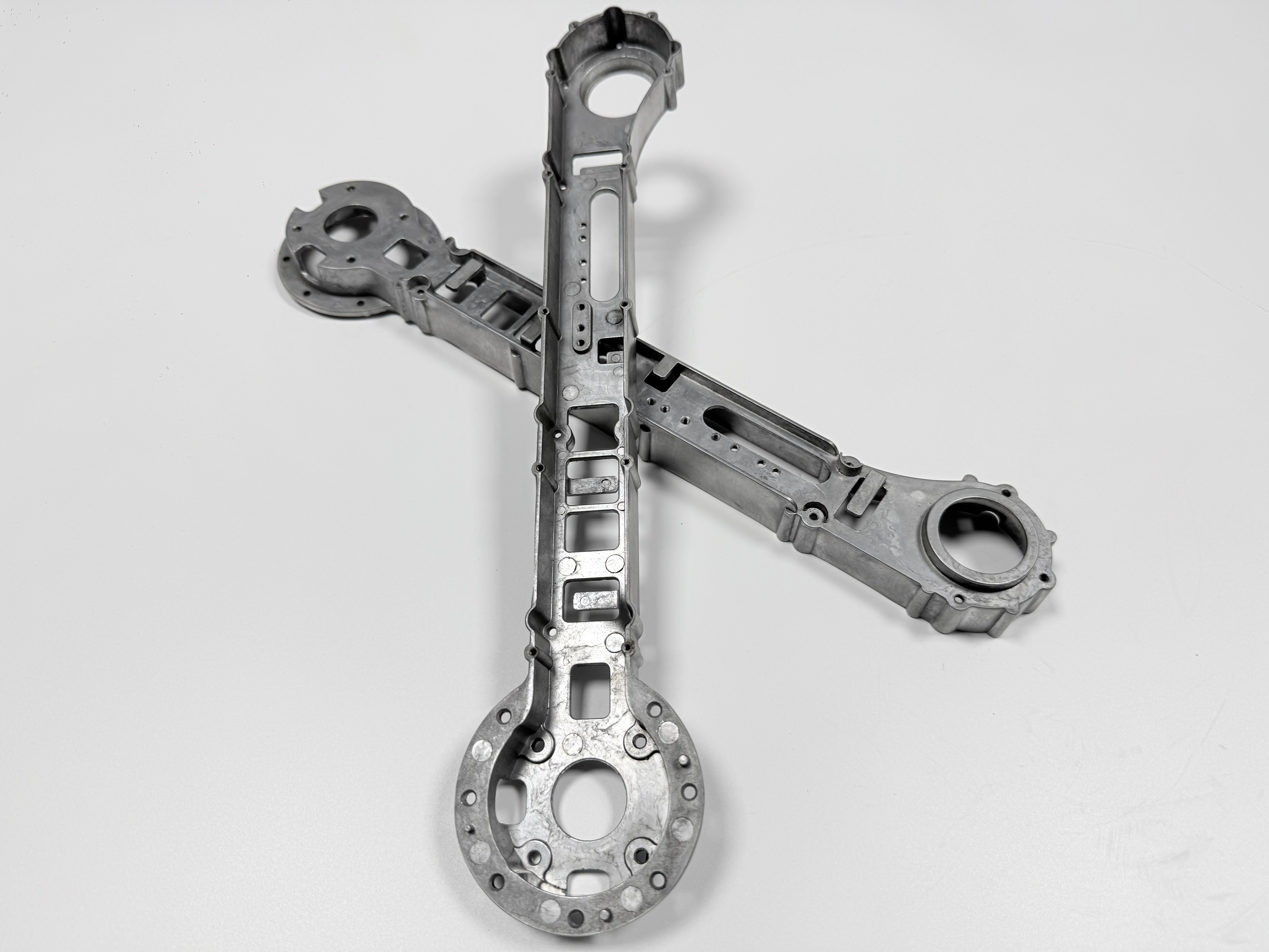
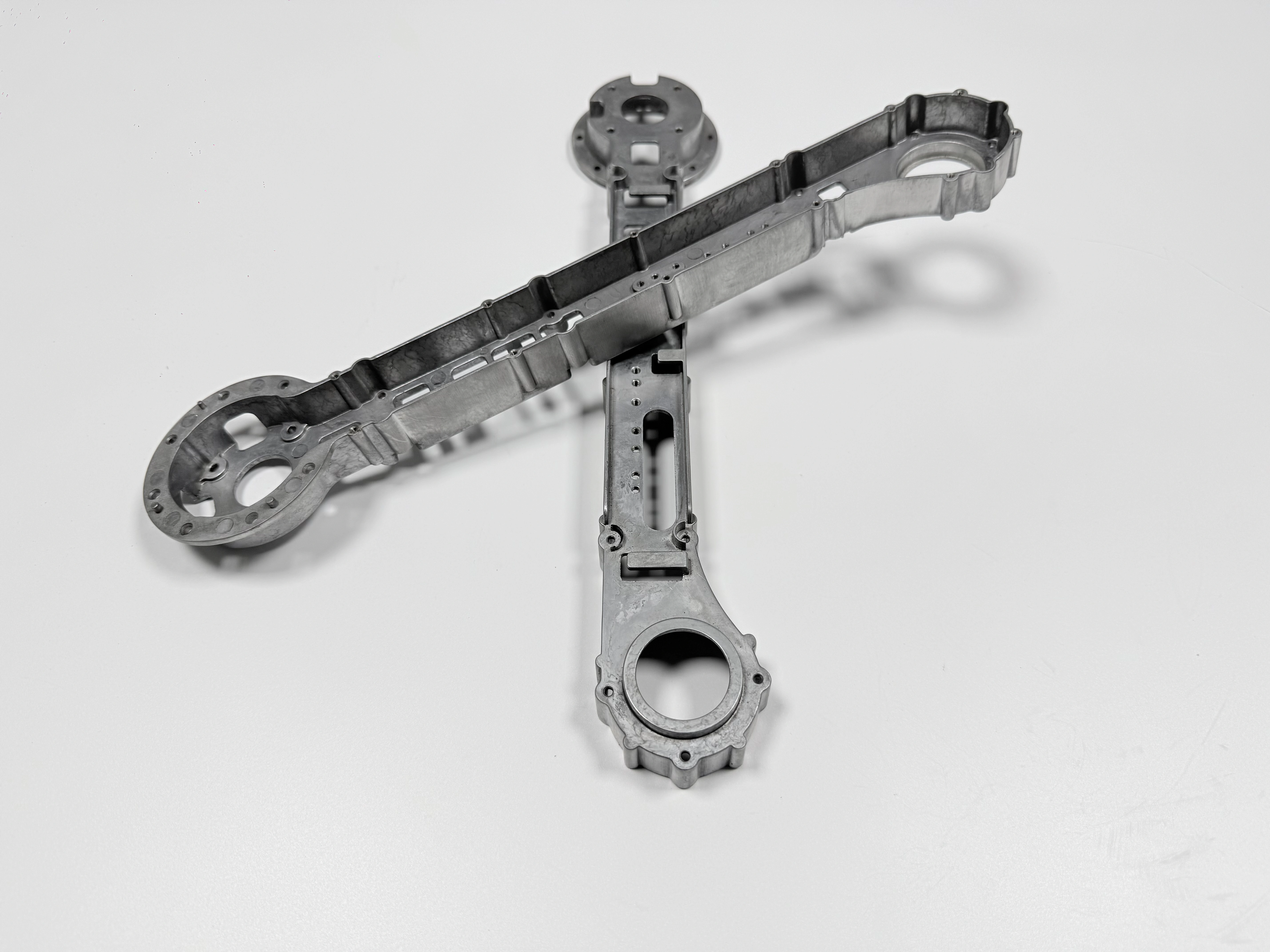
The Part: 320×180×90 mm at 1.2–1.8 kg
The part is a joint frame for an industrial exoskeleton, not a cosmetic cover. The alloy is ADC12, the grade that maps close to A383 under ASTM B85. The route reads vacuum die casting, gate removal, T6, straightening, CNC finishing, MAO with masking, then final inspection.
The wall at the joint boss runs 1.5 mm. The two joint seats carry the ±0.02 mm callout, and the exterior carries MAO film for a floor with cutting fluid and humidity.
Every number here is a drawing target, not a measured value from a released lot. This record is a process example, not a customer program.
Conflict One: 1.5 mm Wall Against 400 MPa
400 MPa is a target after T6, not an as-cast property of ADC12. Reaching it needs solution treatment at 490–510 °C and aging at 150–170 °C. Gas trapped during fill expands at solution temperature, so a blister on a loaded face is a structural defect.
Filling 1.5 mm sharpens that problem. Metal reaches the far end of the wall late and cool, so the last metal to arrive has the least heat to fuse. Vacuum, one cavity, and an overflow at that end widen the window. A faster shot alone can fold more gas into the same wall. Those choices belong to vacuum die tooling and are fixed before the first shot.
A test bar does not cover this. A bar poured from the same heat and pulled to ASTM B557 proves chemistry and treatment, not a cold shut at the far end of a 1.5 mm wall, because the bar is not thin.
Where the wall can thicken and the 400 MPa target can drop, T6 becomes optional and the blister risk leaves with it.
Conflict Two: Quench Against ±0.02 mm
The quench after solution treatment cools the 1.5 mm wall before the joint boss. The boss transforms last and stops moving last. A seat cut before that movement ends will not hold ±0.02 mm.
Straightening between T6 and the cut answers that. It pulls the frame back inside the machining allowance while the part can still move without cracking. CNC post-machining then cuts the seats from a corrected blank, and a CMM point map reads them from a machined pad.
That datum is half the fix. A 1.5 mm as-cast wall moves under clamp load, so it cannot carry ±0.02 mm or 0.03 mm flatness. The datum goes on a pad that will be cut, and the heat treatment behind that pad sets the stock it needs.
The cut releases stress straightening left behind. An even layer from both sides releases little. A heavy layer from one side can walk the seat after the final pass.
Conflict Three: MAO Film Against Fits
MAO coating grows film out of the aluminum instead of plating onto it, so the film rises above the original surface and also consumes some of it. Threads and fits around a coated face keep their dimensions while the space between them shrinks. A fit cut to ±0.02 mm at CNC is not that fit after coating.
The drawing, not the coating shop, decides what stays bare. Four items go on the mask list: threads, fits, grounding pads, and datums. A list passed by email is not a mask list, because the shop coats what the drawing shows.
Masking protects a face, not a tolerance. A masked seat still needs a check after coating, since tape lifts, plugs shift, and film creeps under an edge.
The boundary runs both ways. A thread that can be reamed after coating does not need masking. A small thread in a tight class does, because reaming may take more than the thread can lose.
First Batch: Blisters After T6, Threads After MAO
In the example run behind this record, two defects arrived in sequence. After T6, blisters showed on the thin-wall face near the far end of fill. After MAO, the go gauge stopped on threads that had been coated.
Both fit the route rather than an operator error. The blister follows gas the fill trapped, and the gauge follows film that grew into an unmasked thread. Neither defect appears on the test bar report or at the casting stage.
The bar met its target while the wall did not. A release built on the bar alone would have shipped the frame, and assembly would have found the thread.
The run was held. Both findings stay as example records without a rate, because a rate from one batch would read as a capability figure.
What Changed: Vacuum, Straightening, Masking, Reaming
Four changes went into the next layout, one per failure. Vacuum die casting and one cavity cut the gas that feeds blisters. Straightening between quench and cut gives the seats a corrected blank. A mask list on the drawing keeps film out of threads, fits, grounds, and datums. Reaming covers threads that still take film.
Each change buys one thing and costs another. Vacuum and a single cavity raise the cost per shot and tie the program to one die. Straightening adds a press and a check between two operations that once ran back to back. Masking adds work at the coating line and a recheck. Reaming adds an operation and leaves bare aluminum in the thread, which needs a touch-up decision.
Order carries the rest. Gate removal before T6 keeps the gate from feeding a blister at solution temperature. Straightening before CNC means the cut meets a corrected part. MAO after CNC keeps the last operation from cutting the film away. The route behind those steps is set out in robot frame die casting.
Result Against the Six Methods
Release was rewritten as four gates over six checks, listed below. Soundness takes a same-heat bar pulled to ASTM B557 against the 400 MPa target, plus X-ray or CT at the thin-wall far end. Geometry takes CMM point maps for the seat, flatness, and hole position. Threads take a go/no-go gauge after coating. The film takes thickness on masked and bare zones, plus salt spray.
The gates are not interchangeable. A bar can pass while the wall blisters. A seat can read inside ±0.02 mm and still walk after the final cut. A thread can pass the gauge and fail at assembly if the wrong feature was masked.
Gate | Check | Limit | Unit | Method |
|---|---|---|---|---|
1 | Same-heat test bar, tensile | 400 target | MPa | ASTM B557 |
1 | Gas porosity at far end of wall | no cold shut or short fill | n/a | X-ray or CT |
2 | Joint seat position | ±0.02 | mm | CMM point map |
2 | Seat flatness | 0.03 max | mm | CMM |
2 | Hole position | ±0.02 | mm | CMM |
3 | Thread after MAO | go gauge passes | n/a | go/no-go gauge |
4 | MAO film, masked and bare zones | recorded per lot | n/a | film thickness gauge |
4 | Salt spray, coated face | duration set on drawing | n/a | salt spray cabinet |
Measured values from the example run stay in the project report. This page keeps the criteria, the method, and the order, and publishes no yield. The ADC12 HPDC case runs the same gate logic on a thicker part.
What This Case Does Not Prove
The record is an example. It carries no customer name, no batch size, no price, no lead time, and no yield, and it cannot be quoted as a capability figure.
It does not prove that ADC12 reaches 400 MPa at 1.5 mm on another frame. Section, gate position, vacuum, and heat treatment change with the part, and a bar that passes on one frame says nothing about the next drawing.
T6 stays a window, 490–510 °C solution and 150–170 °C aging, subject to plant confirmation. Film thickness and salt spray duration stay inspection items, not numbers.
What it does show is narrower. The three conflicts meet on one part, and the order of the gates keeps them apart.