Bearing Bore Machining in Cast Housings: Alignment, Fit and Inspection Planning
Bearing bore machining in cast housings must control more than nominal diameter. The bearing system can depend on housing fit, roundness, cylindricity, axis location, relationship between two seats, surface texture, remaining wall, housing stiffness, operating temperature and assembly force. A bore can pass a two-point diameter check while being lobed, tapered or misaligned.
The fit should come from the bearing manufacturer and product engineering using bearing type, ring load, housing material, duty, temperature, speed, vibration, retention and service requirements. An aluminum casting expands differently from a steel bearing ring and can relax under press load. This article does not prescribe a universal H7 tolerance or interference.
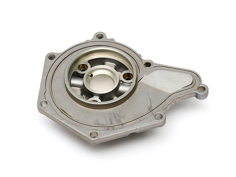
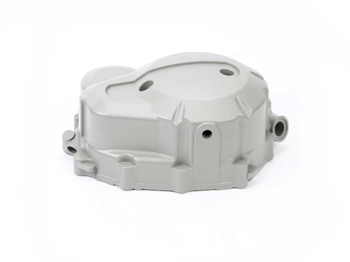
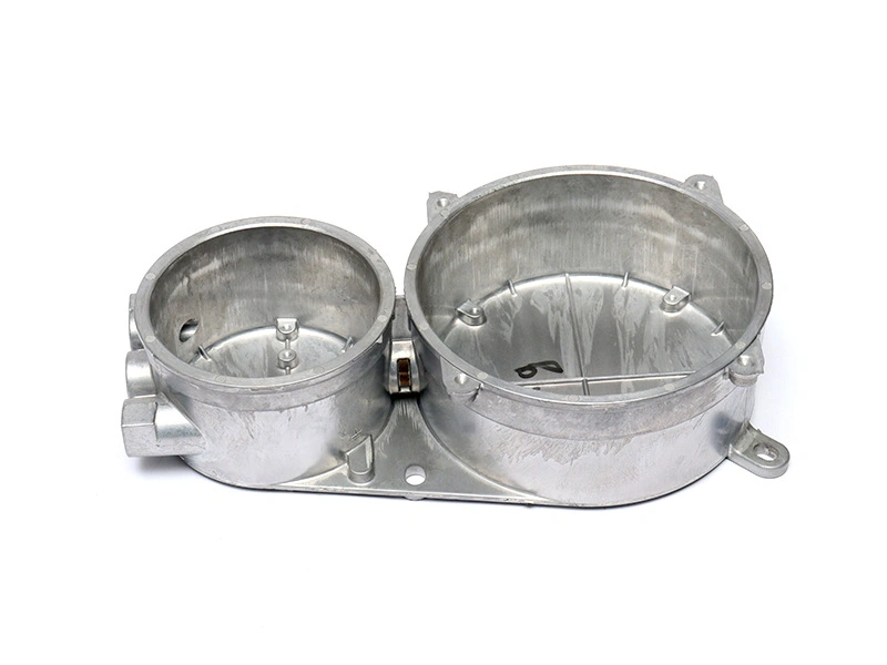
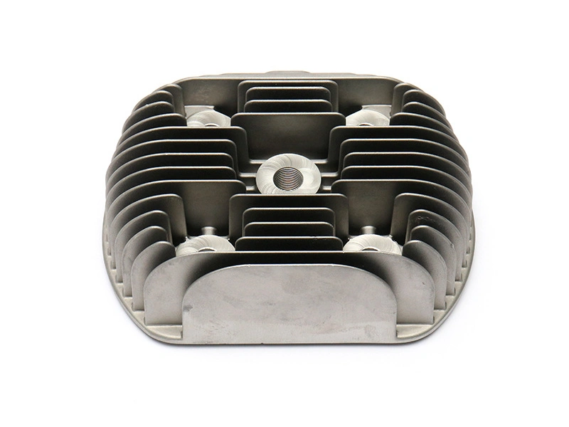
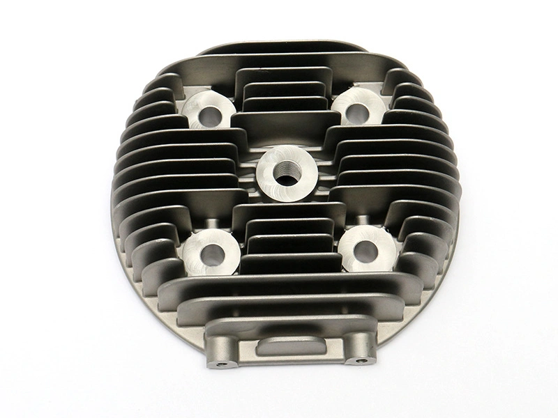
The images show circular bore-type interfaces and mounting holes from different views. They do not confirm that the parts are bearing housings or demonstrate bore performance.
Which Bearing-System Inputs Control the Housing Bore?
Start with bearing designation and tolerance, which ring rotates relative to load, expected load and shock, speed, temperature range, lubrication, housing material and stiffness, retention method, assembly route and required life/noise behavior. A stationary outer ring under a rotating load can need different anti-creep control from a ring under a stationary load. Split housings, thin housings and inserted seats add other constraints.
System Input | Bore Decision Affected | Evidence Source |
|---|---|---|
Bearing tolerance/outer-ring design | Housing fit and usable bore range | Bearing manufacturer data |
Load direction and ring creep risk | Clearance versus interference direction | Product load analysis |
Temperature | Differential expansion and internal clearance | Thermal operating envelope |
Aluminum housing stiffness | Press distortion and support continuity | Geometry/material validation |
Assembly method | Chamfer, lead-in and force limits | Production press/thermal plan |
Service and maintenance | Retention, removal and corrosion protection | Product lifecycle requirement |
Use the bearing supplier's current recommendation and verify the full tolerance stack. A nominal interference computed from midpoint values can disappear or become excessive at material and temperature extremes.
How Size, Form, Orientation and Location Differ
Diameter controls size. Roundness controls each circular section. Cylindricity controls the complete cylindrical form without a datum. Axis orientation and position control the bore relative to functional datums. Coaxial or common-axis function between separated bores should be expressed using the selected drawing standard and datum strategy rather than a vague “concentricity” note.
A bore gauge can report a diameter at one depth and direction while missing taper or lobing. CMM points can evaluate axis and form but require sufficient strategy and stable datum alignment. Surface texture influences fit and material displacement during press assembly, but Ra does not describe form.
Characteristic | Failure if Weak | Inspection Direction |
|---|---|---|
Diameter | Wrong fit or assembly force | Multiple depths/directions or production gauge |
Roundness | Uneven ring support and local stress | Roundness-capable method |
Cylindricity/taper | Partial axial contact | Full-depth variable measurement |
Axis position/orientation | Gear, shaft or seal misalignment | Datum-based CMM/gauge |
Surface texture | Fit variation, fretting or insertion damage | Defined Ra/Rz/lay method |
How Machining Stock and First-Operation Datums Support the Bore
Stock must clean the cast core or pin surface across cavity and lot variation while preserving minimum wall and avoiding unnecessary exposure of subsurface voids. Map actual as-cast bore position and diameter relative to functional casting targets. Uneven stock can deflect tools, shift the finished bore and create different wall stiffness around the circumference.
Operation one should establish a face, pilot bore or other durable references tied to assembly. Later boring should locate from those datums with controlled pins and supports. If two bearing seats share an axis, machining them in one setup or from a common bar can reduce transfer, but access and tool deflection must be verified.
Planning Item | Required Evidence | Risk |
|---|---|---|
As-cast bore map | Cavity/lot center and stock distribution | Incomplete cleanup or deep one-sided cut |
Datum chain | Assembly frame to first/later operations | Consistent bore in wrong position |
Remaining wall | Minimum section after finish | Distortion or pressure/structural weakness |
Core/porosity region | Distribution and machining-depth review | Opened void at bearing seat |
Tool access | Bar length, support and chip evacuation | Taper, chatter and recutting |
The aluminum die casting design should include stable fixture pads and enough stiffness around the seat. A late bore shift can invalidate casting and tooling evidence.
When Boring, Reaming or Additional Finishing May Fit
Boring can correct location and produce controlled size/form when the machine, bar and fixture are stable. Reaming follows an existing hole and is efficient for size/finish but has limited ability to correct a significantly misplaced or uneven bore. Fine boring can finish precision seats. Honing or another finishing method may be considered when the bearing system needs a form/texture result that the preceding route cannot achieve, but it adds stock, cleanliness and process control.
CNC post-machining for assembly fit provides broader process context; the bearing seat still needs its own size, form and axis evidence.
Process | Strength | Boundary |
|---|---|---|
Rough/semi-finish boring | Removes uneven stock and establishes axis | Bar stiffness, heat and tool force |
Finish boring | Controlled size/location in stable setup | Tool wear and thermal drift |
Reaming | Efficient sizing and finish | Follows pre-hole and can produce lobing |
Honing if justified | Can refine form/texture | Added allowance, cleanliness and axis control |
Single-pass common-bar concept | Supports two-bore alignment | Access, deflection and long-tool stability |
Process names do not guarantee capability. Validate on production-intent casting stock, tool-life boundaries and warm operating conditions. Guidance on CNC machining die cast parts provides context; the bore control plan must remain part specific.
How Thin Walls, Clamping, Heat and Springback Change the Bore
Clamps can ovalize a thin seat or pull a flange flat. The cutter produces a round bore in the restrained state, and the bore becomes lobed after release. Supports and clamp contacts should route force through stiff ribs or bosses, not across the bore wall. Use minimum stable force and measure clamped versus free form.
Cutting heat expands aluminum. A warm bore can measure differently after cooling, and tool/bar growth can shift size through a run. Coolant, cycle time, machine warm-up and gauge temperature need controlled conditions. Compensation should follow measured trends and not hide unstable tool wear.
Source | Bore Signal | Control |
|---|---|---|
Clamp across thin wall | Free-state lobing | Supported force path and force sweep |
Uneven stock | Tool deflection and position shift | Stock map and staged cut |
Tool/bar heat | Diameter trend over cycle | Warm-up, coolant and offset discipline |
Residual stress release | Form changes after material removal | Rough/relax/finish trial if needed |
Chip recutting | Scratch, taper or built-up edge | Evacuation and tool inspection |
How Assembly Temperature, Coatings, Burrs and Press Force Affect Fit
Press assembly needs a lead-in that guides the bearing without shaving aluminum or loading through rolling elements. Force should be applied to the correct ring according to bearing instructions. Track force versus displacement; an early spike can indicate burr, misalignment or excessive interference, while unusually low force can indicate oversize or damaged support.
Thermal assembly can reduce insertion force, but housing and bearing temperatures, soak, condensation and material limits need control. The final retained fit at service temperature remains the requirement. Coating or corrosion protection should not enter the seat unless designed and qualified; thickness variation and edge buildup change fit. Mask residue and chips must be removed.
After assembly, verify seating depth, rotation/noise or other product function as specified. A successful press does not prove bore alignment or life, and a diameter pass does not prove the assembly avoided damage.
How Bore Gauges, Air Gauges, CMM and Masters Differ
A dial bore gauge is flexible and can measure multiple depths and directions, but operator rocking and master setting matter. Air gauging is fast and sensitive for production size/form signatures in its calibrated range, but jets average a region and require clean dry air, master control and geometry-specific tooling. CMM measures location, orientation and form with a suitable point strategy, but cycle time and stylus access can limit production use.
A functional plug or master can verify assembly envelope but may not reveal taper, local lobing or why a part fails. Roundness equipment can provide high-quality form data during qualification. Correlate production gauges with CMM/roundness and press results using shared parts.
Method | Best Use | Main Limitation |
|---|---|---|
Dial bore gauge | Size at several depths/directions | Operator and no direct axis location |
Air gauge | Fast production size/form trend | Master, air and jet averaging |
CMM | Datum-based axis position/alignment | Point density and datum simulation |
Roundness instrument | Detailed form analysis | Setup and production throughput |
Functional master | Quick envelope/assembly check | Pass/fail with limited diagnosis |
The CMM method should use the released datum frame. Gauge R&R or a suitable measurement-system study should include part loading, master setting and temperature.
Hypothetical Common-Axis Plan for Two Bore-Type Interfaces
Consider a hypothetical flange casting with two separated bore-type interfaces intended to support one rotating assembly. Operation one creates a mounting face, pilot reference and clocking feature from stable cast pads. Operation two seats on the face and uses the pilot/clock to rough both bores. A common-bar or same-setup finishing concept is compared with two setups through an alignment error budget.
Released parts are measured at several depths and directions, then CMM evaluates both axes to the functional datum frame. Clamp-force and warm/cool studies confirm free-state form. Production gauges are correlated to the variable data, and assembly force/functional trials are run on boundary samples.
This is a hypothetical planning example. It does not identify the pictured part as a bearing housing.
What to Include in a Bearing-Bore Machining RFQ
Provide bearing manufacturer data, load and ring condition, speed, temperature, lubrication, housing material and treatment, assembly/retention method, mating shaft or gear relationships, 3D/2D drawings, datum scheme, stock, quantity, cleanliness and required inspection. State whether free-state and assembled results are both needed.
For CNC machining, request the datum/fixture concept, stock map, boring/finishing route, clamp and thermal controls, gauge plan, press/thermal assembly trial and change controls. The supplier should not substitute a nominal fit based on experience for bearing-system approval.
RFQ Item | Buyer Defines | Supplier Returns |
|---|---|---|
Fit basis | Bearing, load, temperature and material inputs | Proposed bore tolerance review |
Geometry | Size, form, axis and datum controls | Machining/inspection capability plan |
Stock | Casting definition and minimum wall | Cavity/lot cleanup evidence |
Assembly | Press/thermal route and force limit | Lead-in, force monitoring and trial |
Inspection | Sampling, reports and functional checks | Gauge correlation and MSA |
Change control | Tooling, bearing and finish notification | Requalification triggers |
A reliable bearing-bore-type interface combines the approved fit with controlled form, axis relationship, free-state stability, clean assembly and correlated inspection. Diameter is essential, but it is only one part of the functional seat.
How Bearing Creep, Retention and Service Removal Affect the Seat
If the outer ring moves relative to the housing under load, fretting, heat and wear can enlarge or polish the seat. Fit selection is the first defense where required, but shoulders, covers, snap rings or qualified retaining compounds may control axial movement or supplement anti-creep behavior. Each feature adds machining and inspection relationships: shoulder squareness, retaining-groove geometry, cover-face position and adhesive gap/cleanliness.
Too much retention can create other failures. Excessive interference can reduce internal clearance and distort raceways. A cover can preload a bearing unintentionally. Retaining compound can enter rolling elements or prevent service removal. Product engineering should specify whether the bearing is replaceable and what housing damage is acceptable during removal.
Retention Element | Machining Requirement | Validation |
|---|---|---|
Housing interference | Size, form, texture and thermal stack | Press/thermal assembly and bearing function |
Axial shoulder | Face location, squareness and clean corner | Full seating without ring edge load |
Cover/retainer | Bolt pattern and controlled axial gap | No unintended preload or movement |
Snap-ring groove | Width, depth, edge and location | Ring seating and load capacity |
Retaining compound | Gap, texture and compatible cleanliness | Cure, temperature, fluid and removal |
During durability evaluation, inspect evidence of ring movement, fretting debris, seat polish, bore growth and loss of retention. A successful initial press curve cannot prove service stability. If removal and replacement are required, repeat bore inspection after the approved extraction method to confirm the aluminum seat has not galled or expanded beyond its reusable condition.
How to Qualify First Article, Pilot and Production Capability
First article should include a complete stock map, datum chain, multi-depth/multi-direction size, roundness and cylindricity where required, axis position, texture, burr/porosity inspection, temperature and clamp state. One part from one cavity is insufficient. Include representative cavity and stock extremes and the intended tool-life boundary.
A pilot batch tests part-to-part stability, machine warm-up, offset practice, tool wear, gauge loading and assembly force. Stratify results by casting cavity, fixture pocket, cutter and time. Combined capability can hide one cavity with uneven stock or one nest that ovalizes the seat. Confirm gauge correlation before reducing inspection frequency.
Stage | Evidence | Release Decision |
|---|---|---|
Process development | Stock, toolpath, clamp and thermal trials | Select stable machining window |
First article | Full geometry and datum report | Confirm drawing compliance |
Pilot batch | Cavity/fixture/tool-life variation | Confirm short-run capability |
Assembly trial | Force/displacement and function at boundaries | Confirm fit system |
Routine production | Fast gauge trends plus periodic audits | Maintain qualified state |
Change triggers include bearing supplier or designation, housing alloy/heat condition, casting tool repair near the seat, stock/datum change, fixture service, cutter or finishing route, coating at the bore, assembly method and gauge system. Revalidation should cover the characteristics affected, not merely repeat one diameter check.
How to Investigate Bearing-Seat and Assembly Failures
Preserve the housing, bearing, press curve, temperatures, lubricant or retaining material, machining and gauge records. A high insertion force can result from small diameter, burr, taper, axis misalignment or cold temperature. Low retention can result from oversize, lobing, housing relaxation, temperature or contaminated compound. Noise can involve ring distortion, two-bore misalignment, shaft or bearing damage.
Map wear or contact around the ring and seat before cleaning. Measure housing free state after careful approved removal and compare with preassembly data. Section or image suspect porosity only when it addresses the observed mechanism. Do not automatically enlarge a bore after one assembly complaint; that correction can reduce retention on the rest of production.
Failure Signal | Competing Causes | Evidence to Preserve |
|---|---|---|
High press force | Fit, burr, taper, alignment, temperature | Force curve, bore map and lead-in |
Bearing creep | Loose fit, load, heat, housing relaxation | Contact marks and service condition |
Noise/heat | Ring distortion, axis error, preload, bearing damage | Post-assembly form and functional data |
Cracked housing | Excess interference, thin wall, defect, assembly shock | Fracture location, press and section evidence |
Early wear | Misalignment, contamination or support loss | Two-bore axis and lubricant/debris record |
Corrective trials should isolate one credible cause and repeat the complete fit, form and assembly evidence. A passing replacement bearing alone cannot show whether the housing process is stable.
Boundary-sample assembly should include more than the smallest and largest mean diameters. Select parts that represent maximum permitted roundness, taper, axis error and free-state change, because each can produce a different press-force curve and ring distortion. Use one controlled bearing population or measure bearing outer diameters so housing and bearing variation are not confused. Record insertion speed, alignment, lubricant, part temperatures and force versus distance.
After assembly, check the function that justified the bore controls: rotation torque, runout, noise, retention or another released measure. A housing can pass insertion force while distorting the outer ring, or show a high peak from a burr despite acceptable bore form. Linking geometry, force trace and final function creates a defensible production window and gives failure analysis a baseline that one diameter result cannot provide.
FAQ
How Should a Bearing Fit Be Selected for an Aluminum Cast Housing?
Why Can a Bore Pass Diameter Inspection but Fail Roundness or Assembly?
How Should Two Bearing Bores Be Machined and Inspected for Alignment?
What Fixture Errors Distort a Thin-Wall Bearing Seat During Machining?
Which Bore Inspection Method Is Best for Production Release?