A356-T6 Split Bearing Housings: Wall, Bore, Stress Relief
A356-T6 is the alloy this split bearing housing is drawn in. The grade answers four questions at once: whether a 5–8 mm wall fills in a steel mold, how the part moves through the temper cycle, whether the Ø60 H8 bore machines clean, and how the casting behaves indoors. The metal is ordered as aluminum alloy to A356 (AlSi7Mg, GB/T 1173 ZL101A) in the T6 temper.
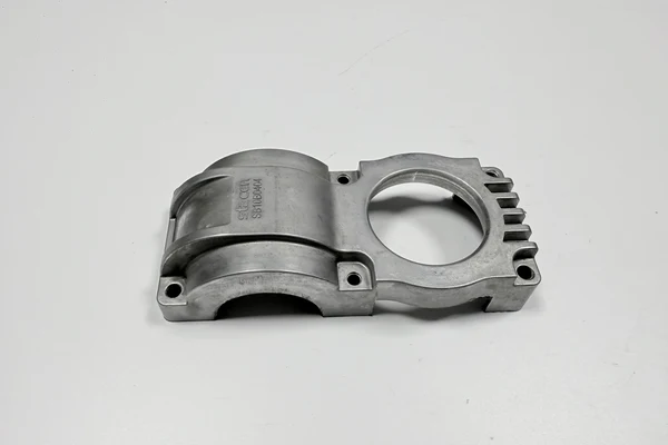
The drawing fixes 120×95×70 mm, 420±30 g and a Ø60 H8 bore. Those are targets, not readings, and they are the numbers the mold, the pour, the quench and the boring pass are held to. Every figure below is a drawing target, a typical value, or a range the foundry has yet to confirm.
Why does A356 suit a split bearing housing?
A356 suits the housing because its silicon level carries fluidity into a 5–8 mm section and its magnesium makes a T6 temper possible. A steel mold pulls heat out through both faces of the wall, so the section sets from each side while the runner still feeds it. Pour runs at 700–740 °C into a mold preheated to 250–350 °C, a typical range that still waits on foundry sign-off.
The alloy is not picked for hardness. It is picked because the seat and the bore are cut after casting, and a grade that fills the section without cold shuts leaves the boring tool sound metal. The same logic runs through A356 brackets for battery modules, where a thin section and a machined interface share one drawing.
What does T6 change in a 5–8 mm wall?
T6 adds a solution treatment at 535–545 °C, a water quench and an age at 155–165 °C for 4–6 h, a typical range pending foundry sign-off. The quench is where a thin wall earns its keep and where it pays back: the section cools fast enough to take the temper, and fast enough to distort.
A 5–8 mm wall cannot cool evenly, because the seat end holds more mass than the flange. The bore and the split faces move after the quench, which is why both are cut afterwards. Because the quench comes before machining, the movement is removed as stock rather than straightened.
Why is A356 the same family as ZL101A?
ZL101A is the GB/T 1173 designation for the same Al-Si-Mg family as A356, so a drawing may carry either name and a certificate may carry both. A356 names the alloy, ZL101A names it in the Chinese standard, and T6 names the temper.
A drawing that says only A356 leaves the standard and the temper open, and the foundry then supplies what its own route supports. Name alloy, standard and temper on one line, and the certificate, the heat-treat cycle and the quote basis follow from it.
What does a fixed density mean for a 420 g housing?
Density belongs to the grade, so weight is set by volume. At a 120×95×70 mm envelope the 420±30 g target is a wall budget. The 5–8 mm section and the mass around the half-round seat decide it, and a change of wall moves the weight further than a change of alloy within the family.
One calculation keeps the weight honest. The envelope measures 798 cm³, and 420 g spread over it averages 0.53 g for every cm³ of envelope, with the ±30 g band moving that between 0.49 and 0.56. The arithmetic runs on nominal dimensions rather than a casting weight, and a wall change moves it before a change of alloy does.
That is why the drawing carries both figures. A buyer who compares housings by weight is comparing wall sections, and a foundry that prices by weight is pricing a pour rather than a bore.
Why does the bore need machining stock?
The cast skin cannot hold Ø60 H8, so the bore arrives with stock and the H8 limits are cut. Stock covers three things: the distortion left by the quench, the mismatch between the two halves, and the clamp load that appears when the halves are bolted.
Because the halves are bored as one body, that stock comes off in a single pass on a single axis. Boring each half alone would leave two axes, and a bearing ring pressed onto two axes wears on one side. The post machining scope carries that setup, and bore alignment planning sets out the datum.
| Feature | Drawing target | Allowed range | Checked with |
|---|---|---|---|
| Wall | 5–8 mm | As drawn | Caliper |
| Weight | 420 g | 420±30 g | Scale |
| Bore | Ø60 H8 | H8 limits as drawn | Inside micrometer, three points |
| Split faces | 0.05 mm flat | Not over 0.05 | Surface plate and feeler gauge |
| Bore to mounting face | 0.05 mm | Within 0.05 | CMM |
| Surface | Sa 2.5 | ISO 8501-1 grade | Comparator |
Why does a thick wall shrink more than a thin one?
Shrink follows mass. The thick end of the 5–8 mm band sits where the wall meets the half-round seat, and that node freezes last, after the feed has sealed. A cavity opens under the face the boring tool will cut, so the foundry passes a sound casting and the machine shop finds a mark.
A hole over Ø1 mm scraps the housing. The call starts by eye and is confirmed with penetrant testing after machining. Because the cure is a riser at the pour, a wall thickened for safety buys a shrink risk and pays for it twice, in metal and in scrap.
What does T6 do to the split faces?
The quench bows the split faces, so the mill pass that makes them flat runs after the temper, not before. Milling the joint first and heat-treating afterwards would move the faces the bore is set from, and the 0.05 mm target would be gone before the boring pass.
The order that holds is T6, then mill the split faces, then bolt the halves, then bore. Flatness at the joint is not a cosmetic call: it is what lets the two halves clamp without pulling the bore out of round.
When does sand-cast aluminum win?
Sand casting wins on envelope and on one-offs: a cheap pattern, thick sections and a surface that needs machining on every face. The 5–8 mm control and the steel-mold skin are what the sand route gives up, and the stock that replaces them is paid per part.
The choice is a volume question, and choosing aluminum for a casting sets out the same trade for other parts. A housing that will never repeat does not need a steel mold, and a housing with a 5–8 mm wall does not want a sand skin under a 0.05 mm bore.
When does cast iron win?
Cast iron takes the job when stiffness outranks weight. The same 120×95×70 mm envelope in iron arrives in a different weight class, and the frame that carries it has to be built for that load. Iron also holds a bore with less section, so a heavy pump or gearbox may still call for it.
The swap costs the 420±30 g budget and changes the corrosion route, because a painted iron housing and a bare blasted aluminum one are maintained differently. A356 keeps the work while the bearing load fits the aluminum section and the housing stays indoors.
Why is anodizing not assumed on this housing?
The final surface is shot blast to Sa 2.5 under ISO 8501-1, and the bore and split faces are left as cut. Anodizing is not confirmed for this part: the drawing does not call it, and a blasted cast face and a machined bore take a coating differently, so it would be a separate specification and a separate cost.
Corrosion cover comes from the alloy and the indoor service instead. The housing runs inside equipment, with oil and vibration, and no outdoor exposure is promised, so a bare blasted surface is the stated finish rather than a step on the way to one.
The casting route behind it is set out under gravity casting, and a cast-then-machined hinge shows the same division between cast faces and cut faces in a hinge project.
FAQ