Gravity Casting a Split Bearing Housing: Walls and Bore
A split bearing housing is cast in a steel mold, split into halves, bolted back together and bored as one body. The gravity casting step fixes the 5–8 mm wall and the feed behind the seat; boring decides whether the bore and the half-round seat share one axis.
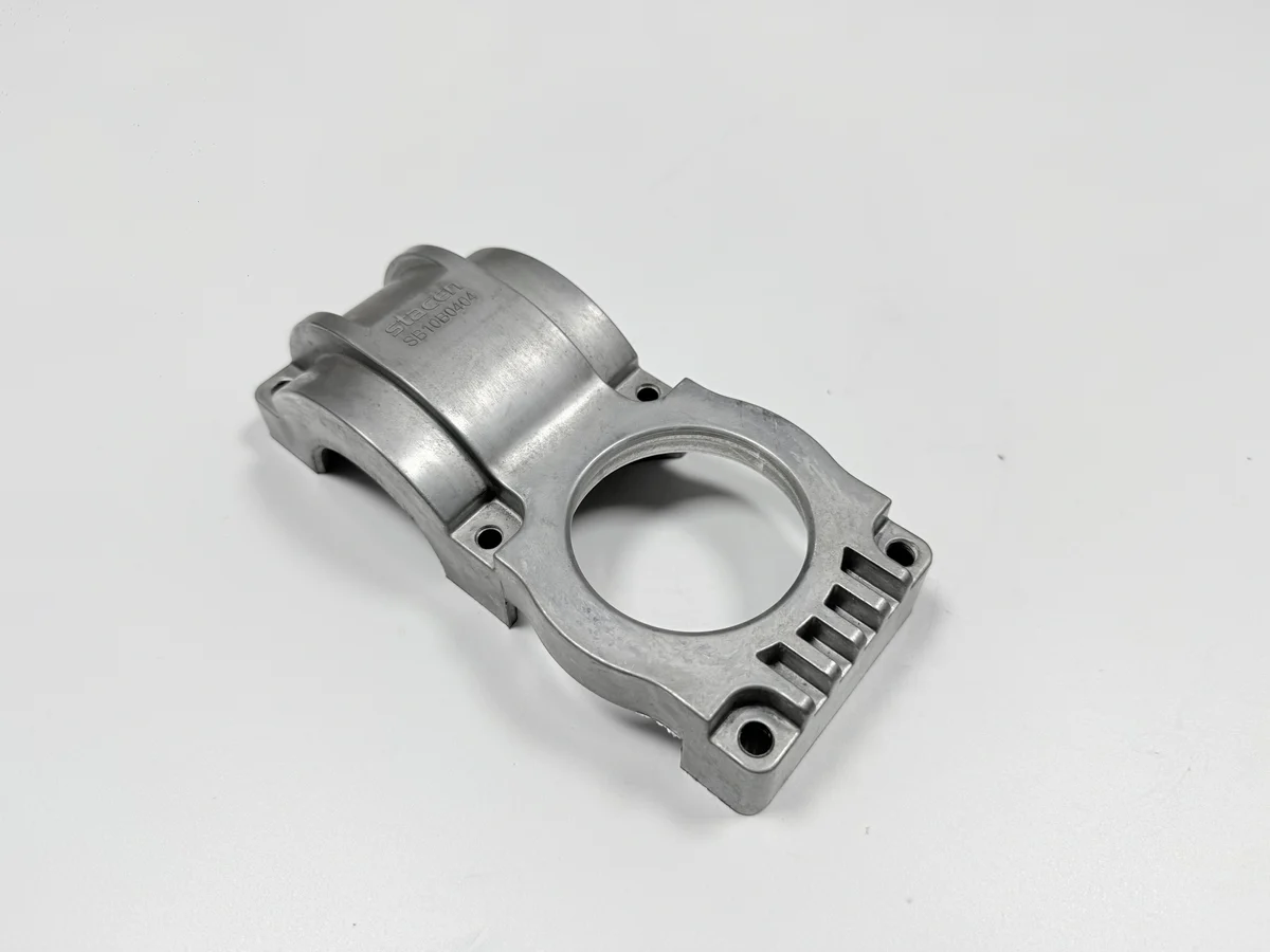
The part is an A356-T6 housing of 120×95×70 mm and 420±30 g, with a Ø60 H8 bore. Every figure there is a drawing target rather than a sample reading, which is the standard the mold, the pour and the boring pass are held to.
What does gravity casting a bearing housing replace?
Gravity casting replaces a sand-cast aluminum housing or a cast iron one, and the swap moves work from the machine shop into the mold. Sand casting needs a cheap pattern and leaves the sections thick, so the housing arrives heavy and gets machined on every face. Iron brings stiffness that aluminum does not, at a weight the frame carries.
The steel-mold route holds while the wall stays near 5–8 mm as drawn and the order is large enough to carry the tool. Sand takes the large envelope or the one-off, and iron takes the case where stiffness outranks weight. This part is drawn for indoor service inside a machine, with oil and vibration and no outdoor exposure promised.
Because the mold is steel and returns to the press, its charge spreads across shots rather than one pattern, so a short run carries more tooling per housing. The trade between routes is a volume question, set out in choosing a casting process on cost.
Why is a steel mold used instead of sand for this housing?
A steel mold is used because it pulls heat through the wall fast enough to hold a 5–8 mm section, and because the same cavity gives back the same shape on every shot. A sand mold is rebuilt for each pour, so the wall drifts with the ramming and the draft.
One permanent mold carries one or two parts per shot, a typical range, still pending foundry sign-off, and its life is counted in shots rather than years.
Which interfaces must the housing hold?
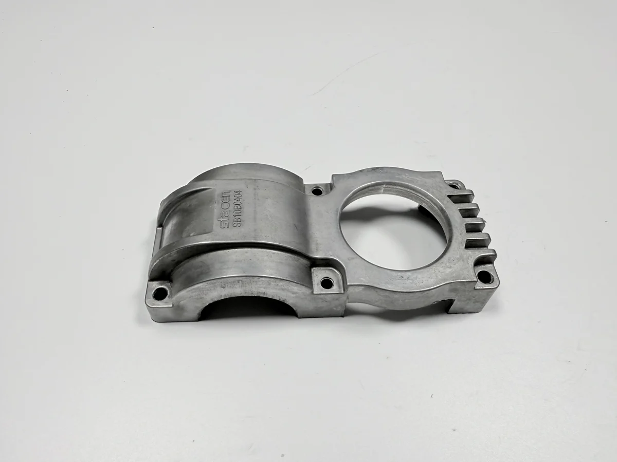
Three interfaces: the Ø60 H8 bore that carries the bearing outer ring, the half-round seat that the cap closes onto, and the mounting face with its four Ø9 holes. The datum is the bore axis with that face, so a reading taken elsewhere describes the fixture.
The seat and the bore share an axis within 0.05 mm, and the bore stands square to the mounting face within 0.05 mm. Both are drawing targets, and both are won in one boring setup.
Which dimensions are fixed before the pattern is made?
Five figures close before the pattern is cut: the bore, flatness of the split faces, squareness of the bore to the mounting face, bolt pattern position and envelope. All five are drawing targets, and all five cost less to change on paper than in steel.
| Feature | Drawing target | Allowed range | Checked with |
|---|---|---|---|
| Bore | Ø60 H8 | H8 limits as drawn | Inside micrometer, three points |
| Split faces | 0.05 mm flat | Not over 0.05 | Surface plate and feeler gauge |
| Bore to mounting face | 0.05 mm | Square within 0.05 | CMM |
| Flange holes | 4×Ø9 | Position Ø0.3 mm | Go/no-go plug and trial fit |
| Envelope | 120×95×70 mm | As drawn | Caliper |
Because a change after the mold is cut is tool work, the drawing has to be signed off first. Boring stock is the usual argument: metal left in the bore can still be cut away, while a bolt pattern drilled off position cannot be pushed back.
How does a 5–8 mm wall fill in a steel mold?
The wall fills while the runner still feeds it, and the steel mold pulls heat out through both faces, so the section sets from each side at once. The alloy is A356 aluminum alloy (AlSi7Mg, GB/T 1173 ZL101A) in the T6 temper, poured at 700–740 °C into a mold preheated to 250–350 °C, a typical range, pending foundry sign-off.
The thick end of that band freezes last, and it sits next to the half-round seat. The 5–8 mm section is not uniform by accident: the seat carries the bearing load, and that thickness is also the mass the feed has to reach last.
Where does the shrink hole form on this housing?
Shrink forms under the half-round seat, at the node where the wall meets the seat, because that mass freezes last and its feed has already sealed. The cavity sits below the face the boring tool will cut, so the first sign is a mark on a machined seat, not a defect at the foundry.
A hole over Ø1 mm scraps the housing, and one at Ø1 mm or under passes where the seat is otherwise sound. The call is made by eye, then confirmed with penetrant testing, and the scrap line belongs in the first-article report rather than a rework note.
The fix sits at the pour, where a riser can still feed the seat node. Because the defect appears after boring, the machining time is spent before it shows, and a quote that prices only the boring pass cannot remove it.
Which faces are machined after casting?
Three features are machined: the split faces are milled, the bore is bored once the halves are bolted, and the four flange holes are drilled. Cast faces keep the blast finish, and each machined face stays as cut.
The chain runs through melting and degassing, the pour, knock-out, gate and riser removal, deburring, blasting, split-face milling, bolted boring, flange drilling and final inspection. Ten steps, with the post machining scope carrying those three cuts.
Milling comes before boring by necessity. A split face cut after the bore would move the axis the bore was set on, and the housing would have to be bored again.
Why are the halves bolted before boring?
The halves are bolted before boring because each half bored alone gives the seat and the bore two axes, and a bearing ring pressed onto two axes wears on one side. Bolting restores the housing to its service shape, and one pass cuts both halves onto a single axis.
The product sheet places the half-round seat in that same setup, which is how the 0.05 mm coaxiality target is reached; that sequence still waits on confirmation. Coaxiality is read on a CMM from the bore axis and the mounting face, and a trial fit proves the bearing goes in, not that the ring sits on one axis.
Because the bolt-up, the boring pass and the unbolting are three stations, the step costs more than a single pass. That difference belongs in the quote, and a comparison without it tests two different processes.
Why does blasting come before machining?
Blasting comes before machining because the shot reaches every cast face while the split faces and the bore are still stock. Sa 2.5 to ISO 8501-1 is the finish on those cast surfaces, and the machined faces are not blasted at all.
Reverse the two and the shot pits the faces that carry the bearing and the joint. Restoring them means masking before the blast or cutting again after it, on a part whose limits are already 0.05 mm.
That order also decides what the blast is quoted against: cast surface area, not the whole part, since the machined faces never see the shot.
Which tests release a bearing housing?
Six checks release the housing. CMM settles squareness and coaxiality, a three-point micrometer measures the bore, and a plate and feeler test the split faces. Plugs and a trial fit prove the flange holes, penetrant finds an open seat, and a roughness check closes the machined faces.
| Check | Accepted when | Gauge |
|---|---|---|
| Bore and ovality | 0.03 mm maximum | Three-point inside micrometer |
| Squareness | 0.05 mm maximum | CMM, mounting face as datum |
| Coaxiality | 0.05 mm maximum | CMM, bore axis as datum |
| Split faces | Flat within 0.05 | Plate and feeler |
| Bolt holes | Plugs pass, part fits | Go/no-go and trial fit |
| Seat | No open shrink past Ø1 mm | Eye, then penetrant |
Ovality and squareness settle most arguments, because both move when the part is clamped. A bore measured in the fixture reads one value and the same bore released reads another, so the report has to name the state it measured.
Penetrant testing covers what the eye misses: a cavity that reaches the machined face but reads as a smear under a lamp. It has one limit worth writing into the drawing, because a cavity that stays closed under the skin holds no dye.
How is the bore released after assembly?
The bore is released after the halves are bolted, because the clamp load moves it. Readings taken before bolting describe a free part, while the bore under bolt load is the one the bearing meets.
An example record shows the gap. An oval bore of 0.05 mm read after bolting came back to 0.02 mm through bolted boring and a stress-relief pass, with the pass line still at 0.03 mm.
That recheck belongs on the CMM report with the bolted state named, in the same way CMM inspection is documented for other parts.
What does a bearing-housing quote contain?
Four blocks: the steel mold amortised over shots, casting with degating and deburring, machining with the bolted boring step, and blasting with the release tests. On a 420 g housing the metal is the smallest block, so a quote built on weight misses most of the work.
Each block scales on its own variable, from order quantity to cast area.
Because the boring step carries a bolt-up, a pass and an unbolt with a recheck, it is the block most often missing when two quotes sit side by side. The second is the stress relief, which cannot be recovered after finishing.
Ask for the bolted boring step and the penetrant line by name. One is often quoted as plain machining and the other as inspection, and a housing compared without them is compared on the wrong four blocks. Casting and machining on one order run as one route, shown in a die-cast and machined hinge project and in machining against casting.
FAQ