Why Does 0.05 mm Perpendicularity Fail on a Bored Housing?
A housing misses 0.05 mm perpendicularity when the bore and the mounting face are cut from two different references, because the second setup holds the part by its split face and carries that face's error into the axis. The fault belongs to the post-machining route, and a CMM only reports it.
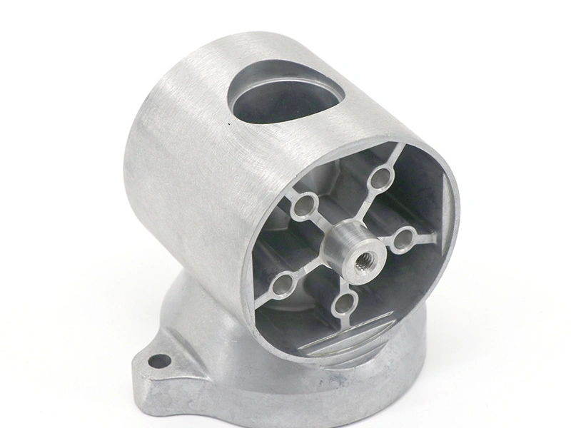
The part is an A356-T6 split housing, 120×95×70 mm with a Ø60 H8 bore, all design targets. A356 (AlSi7Mg, GB/T 1173 ZL101A) halves are cast in a steel mold, blasted to Sa 2.5, milled flat on the split faces, bolted together and bored as one body.
Why does 0.05 mm perpendicularity fail on a bored housing?
A tilt that small hides inside the tolerance until the setup changes hands. The split faces are milled in the first setup and serve as the locating face for the second. The bore is then cut from those jaws, while the drawing locates it from the mounting face, and the distance between the two references shows up as a lean at the bore.
Recutting the bore does not remove that lean, because the next casting repeats the same two references. The fix sits in the datum callout on the drawing, or in one setup that machines the mounting face and the bore without letting go of the part.
Which two setups stack the error?
Setup one mills the split faces to 0.05 mm flatness. Setup two bolts the halves, puts the Ø60 H8 seat on a boring machine and leaves the 4×Ø9 flange holes for a third operation. Each handover re-zeroes the part, and the split face used as a clamp reference is not the face the bearing sits against.
Bolting adds a shift of its own, since the halves close on a face that is flat only within 0.05 mm. A route that prices one boring pass has priced one of those handovers, not the sequence.
What does the mounting face have to do with the bore?
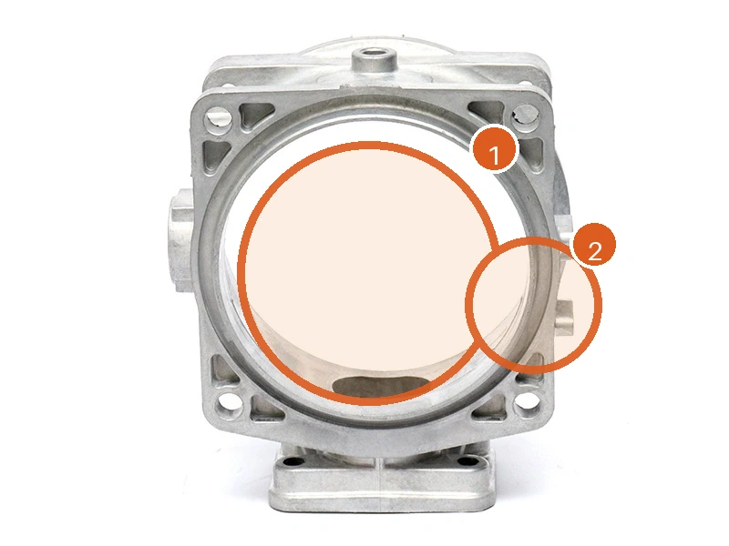
The mounting face carries the four ears that bolt the housing to the frame, and the bore holds the bearing. Squareness between the two decides whether the shaft runs true or binds as it is fitted, and the outer ring wears on one edge when the bore leans.
That face is called out as a datum and machined, not left as cast, because no cast surface holds 0.05 mm. Blasting runs before the split faces are cut, and the machined faces are not blasted afterwards, so the face the housing sits on stays as the boring bar left it.
How is perpendicularity checked on the floor?
A CMM takes the bore axis from several sections and the mounting face as a plane, then reports the deviation against 0.05 mm. A surface plate and a feeler gauge read the split face alone, so a bore that leans still passes that check.
The reading belongs in the first-article report with the datum named, because the same number means something different when it is taken from the split face. A shop that cannot say which face the CMM used has not measured the callout.
Can the split faces be milled after boring?
No. The split face is the reference the bore was cut from, so milling it afterwards removes the material that set the bore position and lets the halves close on a new plane. The bore then has to be recut, and a recut is a second boring pass with its own setup and its own first article.
Order stays as the route card has it: mill the split faces, bolt the halves, bore the seat, drill the flange holes. Any step moved out of that order costs a re-bore, which is the one operation in the sequence that inspection cannot recover.
| Item | Target (mm) | Allowed range | Checked with |
|---|---|---|---|
| Bore to mounting face, perpendicularity | 0.05 | 0.05 max over the bore | CMM |
| Bore diameter | Ø60 H8 | H8 limits on the drawing | Internal micrometer |
| Split face flatness | 0.05 | 0.05 max as drawn | Surface plate and feeler gauge |
| Flange holes | 4×Ø9, position Ø0.3 | Ø0.3 max | Go/no-go gauge, trial fit |
| Wall at the flange | 5–8 | 5–8 as drawn | Drawing, section |
| Machined faces after boring | As cut | No blast after machining | Route card |
Send the drawing with the mounting face named as the datum, the 0.05 mm callout on the bore and the first-article requirement marked, so the quote separates the second setup from the boring itself.