Why Must Both Halves Be Bolted Before the Bore Is Cut?
A split housing is clamped into one body before any boring pass, because the half-round seat and the bore share an axis only while the joint is closed. That order belongs to the post-machining route, and coaxiality at 0.05 mm depends on keeping it.
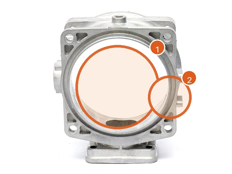
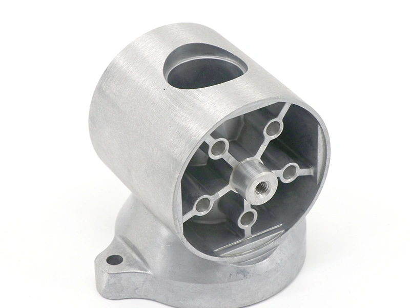
The part is an A356-T6 split housing, the AlSi7Mg alloy listed as GB/T 1173 ZL101A, 120×95×70 mm with a Ø60 H8 bore, all design targets. Gravity-cast halves are milled flat on the split faces, bolted to each other and bored as one body before the 4×Ø9 flange holes are drilled.
Why must both halves be bolted before the bore is cut?
Bolting turns two castings into one workpiece, so the boring bar cuts a single cylinder through both at once. Mismatch between the halves is removed by that cut instead of frozen into it, and the bore comes out round in the assembled state the shaft will see.
A bearing shell presses on the full circumference, so a step at the split line loads one half harder than the other and starts the wear that ends as a loose fit. The alloy arrives in T6, with solution treatment near 535–545 °C and aging at 155–165 °C for 4–6 h, both quoted as typical ranges pending foundry sign-off.
What happens when each half is bored separately?
Every half gets its own axis, and the two meet at the split line at an angle the drawing never allowed. Two half bores that each sit inside the H8 band can still pinch the outer ring out of round once the bolts are drawn up, because the semicircles stop sharing one centre.
That error surfaces late. Assembly feels right, the shaft turns by hand, and the damage appears as edge wear on the outer ring after running hours. Boring each half on a separate boring machine doubles the setups without closing the mismatch.
How is the half-round seat kept coaxial with the bore?
The seat is cut in the same clamping as the bore, which is how the two features hold one axis; that sequence is still pending foundry sign-off on this part. Coaxiality between them carries a 0.05 mm design target, and the number holds only while the part stays in the fixture for both surfaces.
A seat holds the shell before it holds any tolerance of its own. Cut it a little off the bore axis and it pushes the shell against one side of the housing, so the bore measures oval although the bar cut it round.
Which datum does the CMM use for coaxiality?
Reading coaxiality means holding the bore axis as the primary datum and the mounting face as the secondary, the pair the drawing calls for. The number is reported between that axis and the half-round seat, not between the two halves of the bore.
A datum chosen for convenience returns a number nobody can repeat. Align on a split face and the report describes the fixture rather than the part, and the next shift with a different setup will disagree. The pair belongs on the drawing and in the first-article report, with both features named.
How is coaxiality proven before the housing ships?
A CMM report on the bolted pair is the proof, and the reading is taken with the joint closed at the torque the assembly uses. Checking the halves apart answers a question nobody asked, since the fit exists only after the bolts are drawn up.
First article and production check use the same datum pair, so a shift in the reading points at the process rather than the gauge. Bolting adds a setup, an unbolting step and a recheck, and a quote built on two separate boring operations has priced a shorter route than the one that holds 0.05 mm.
| Item | Target (mm) | Allowed range | Checked with |
|---|---|---|---|
| Bore to half-round seat, coaxiality | 0.05 | 0.05 max | CMM |
| Bore diameter | Ø60 H8 | H8 limits on the drawing | Internal micrometer |
| Bore ovality after bolting | 0.03 | 0.03 max | Internal micrometer, three points |
| Split face flatness | 0.05 | 0.05 max as drawn | Surface plate and feeler gauge |
| Flange holes | 4×Ø9, position Ø0.3 | Ø0.3 max | Go/no-go gauge, trial fit |
| Wall at the seat | 5–8 | 5–8 as drawn | Drawing, section |
Send the drawing with the split line, the coaxiality callout and the bolting step marked, so the quote separates the bolted boring pass from the flange drilling that follows it.