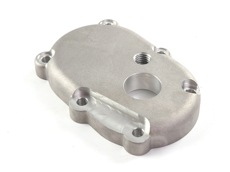
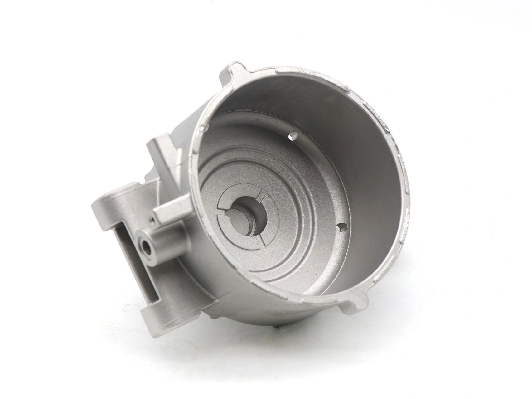
High Pressure Aluminum Die Casting for Precise Custom Metal Parts
High pressure aluminum die casting is a strong production route for precise custom metal parts when a stable design can use a permanent steel die, near-net geometry removes substantial machining or assembly work, and the project can support the tooling investment. It can form thin sections, ribs, bosses, heat-dissipation features and complex exterior surfaces in one shot. It does not make a part precise merely because the metal enters under high pressure.
Precision comes from the complete manufacturing route: an approved alloy specification, a tool built around filling and thermal behavior, controlled casting parameters, defined datums, local CNC machining where required, and inspection in the condition in which the part will be accepted. A dimension measured after trimming may change after machining, coating, thermal exposure or assembly. The drawing and control plan therefore need to state both the requirement and the inspection stage.
For sourcing, treat high pressure aluminum die casting as a linked chain rather than a stand-alone forming operation. The useful question is not whether HPDC can make a complex shape. It is whether the proposed alloy, cavity, process window and downstream route can repeatedly make the required features and provide evidence for the part's real service conditions.
Decide whether HPDC fits the part and program
HPDC usually earns its place when the product design is reasonably mature, repeated demand is credible, and casting can create valuable geometry. Enclosures, frames, covers, brackets and thermal housings are common candidates because the die can integrate walls, ribs, mounting pads and local details. The process is less attractive when nearly every face must be machined, the design changes often, or the specified material condition is available only as wrought stock or through another casting route.
Part size alone does not decide feasibility. Project review must consider projected area, shot capacity, fill distance, section changes, slide travel, ejector support, trim access and the machine available for the selected alloy and tool. A large footprint with shallow walls presents different filling and locking-force questions from a compact casting with deep pockets and heavy bosses. Ask the supplier to identify the assumed machine and cavity arrangement in the quotation.
Project signal | HPDC implication | Evidence before tooling approval |
|---|---|---|
Stable repeated demand | Dedicated tooling may be economically sensible | Demand range, batch pattern, program life and change outlook |
Integrated shell geometry | Near-net casting may replace billet removal or joined pieces | DFM showing parting, draft, ejection, gates, overflows and trim |
Local precision interfaces | As-cast body plus selective CNC may fit | Datum scheme, machining stock, fixture concept and final inspection |
Pressure or fluid boundary | Porosity location becomes a functional risk | Leak medium, pressure, duration, test stage and acceptance limit |
Welding or high-temperature treatment | Conventional HPDC may carry trapped-gas risk | Route-specific trials for the actual alloy, process and thermal cycle |
Frequent engineering changes | Steel-tool revisions can erase the unit-cost advantage | Design freeze plan or comparison with CNC and lower-commitment routes |
Translate precise into controlled characteristics
"Precise" is not an acceptance criterion. The 2D drawing should identify dimensions that control assembly, sealing, bearing alignment, connector position or visual gap. Give each requirement a datum reference, tolerance, surface condition and inspection stage. Use profile or position controls where they communicate function more clearly than a string of coordinate dimensions. The die-casting tolerance plan should separate as-cast capability from machined results.
Dimensional evidence also needs context. A sample from cavity one on a warm, newly adjusted tool cannot qualify every cavity and future production condition. Record the tool revision, cavity, casting machine, alloy batch or heat identification, process settings, trim condition and measurement temperature used for approval. If dimensions are sensitive to coating or stress release during machining, measure at the intermediate stage for process diagnosis and again at the finished-part stage for acceptance.
Do not burden every surface with the tightest requirement on the drawing. Broad tight tolerances increase tool correction, fixture complexity, CNC time, inspection effort and rejection exposure without necessarily improving the product. A buyer gets better control by protecting a small set of functional relationships, then allowing realistic as-cast variation on clearance, hidden and non-mating features.
Use DFM to manage flow, release and distortion
Good HPDC geometry gives molten alloy a feasible path through the cavity and gives the solid casting a stable way out. Keep walls as uniform as function permits, blend unavoidable section changes, and use ribs to create stiffness without turning every junction into a hot mass. Bosses need adequate support and fillets, but heavy boss-to-wall intersections can concentrate heat and shrinkage. Draft, parting-line location and ejector contact must be reviewed on surfaces that affect sealing or appearance.
Thin-wall feasibility depends on more than a nominal wall number. Alloy fluidity, distance from gate, flow splits, vent location, local surface area, die temperature and machine response all matter. Instead of asking for a universal minimum wall, ask the supplier to mark the most difficult fill paths and identify what tool or process evidence will validate them. The same logic applies to tall fins: base thickness, fin spacing, orientation, release and thermal balance determine whether the feature is practical.
A mold-flow analysis can compare gate concepts, air displacement, expected last-fill regions and thermal concentrations before steel is cut. It is a design aid, not proof of production quality. Model assumptions, boundary conditions and material data need review, and trial castings must still confirm fill, porosity distribution, distortion and trim behavior in the physical tool.
Select the alloy with the casting route
A380 is a common North American starting point for conventional aluminum HPDC because it offers a useful manufacturing and property balance. A360 may be reviewed where its corrosion behavior or other specified properties matter, while A413 is associated with high fluidity and is often considered for difficult fill or pressure-containing applications. A383 and ADC12 are also widely discussed for HPDC, but the designations come from different systems and must not be approved as automatic equivalents.
Compare the exact chemical limits, material condition, governing specification, supplier melt practice, machining response, finish compatibility and required properties. A material name on a website is not enough for substitution. The buyer and supplier should document the approved grade and standard, permitted return material or composition controls, certificate requirements and the test route for any property that governs acceptance. The aluminum die-casting alloy comparison is a starting point, not a release document.
A356 is commonly associated with gravity or low-pressure routes and heat-treated casting conditions; it should not be casually added to a conventional HPDC shortlist. If a project calls for A356, T6 properties, high ductility, welding or a demanding thermal cycle, first establish the intended casting process and validation route. Conventional HPDC can contain entrapped gas that expands during solution heat treatment and causes blistering. Specialized vacuum-assisted or structural processes require their own evidence and supplier review.
Build the tool around metal and heat flow
The die is both a shape-making system and a heat exchanger. Gate thickness and location influence fill pattern and freeze-off; runners distribute metal; overflows collect first metal and flow fronts; vents or vacuum paths remove cavity gas; cooling and heating circuits control local solidification. Slides, inserts and ejectors solve geometry and release problems but add interfaces, wear points and maintenance needs. A credible die-cast tooling plan connects these elements to named part risks.
Tool ownership and production responsibility should be explicit. Confirm cavity count, interchangeable inserts, spare components, approved tool steel and heat-treatment route, expected maintenance records, storage, change authorization and what happens if the program transfers. Avoid treating an estimated tool life as a guarantee; life depends on alloy, thermal cycling, geometry, steel condition, process discipline and maintenance. Define inspection and repair triggers based on flash, dimensions, surface condition and other observed changes.
Parting lines, gates, overflows and ejector marks are physical results of the tool. Put their permitted zones on the drawing or approved visual standard before tool design. Moving them after the tool is built may require steel changes or a new insert. The same early decision is needed for traceability marks, cavity identification and date codes so that they remain readable after trimming, machining and coating.
Control filling, solidification and ejection as one window
During production, a lubricated and temperature-conditioned die closes, measured molten alloy enters the shot system, and the plunger advances through controlled stages. The fast phase must fill the cavity before thin regions freeze while avoiding unnecessary turbulence and air entrainment. Intensification pressure then acts while gates remain able to transmit pressure. After sufficient solidification, the die opens, ejectors release the shot, and gates, runners and overflows are trimmed.
Those steps interact. A cold die can cause misruns or cold shuts; excessive local heat can increase soldering, shrinkage or dimensional drift. An unstable slow-shot transition can change the air carried into the cavity. Early ejection can deform weak sections, while delayed release can affect cycle and sticking. Process approval should therefore identify a window for the selected machine and tool rather than one nominal setting copied into a report.
Monitor the variables that explain the part's actual risks. Depending on the machine and project, those may include metal and die temperature, shot profile, pressure response, vacuum level, spray cycle, cooling flow and cycle interruptions. Control limits must come from trials and capability evidence for the named characteristics. A dashboard full of values has little value if changes cannot be tied to cavity-specific dimensions, leakage or defect locations.
Treat porosity as a location and function question
Gas porosity and shrinkage porosity have different causes. Entrapped gas is associated with air, vapor or turbulence captured during filling. Shrinkage forms where metal contracts during solidification without adequate feeding or pressure transmission. Both may exist in one casting, and a polished external surface does not establish internal soundness. Vacuum assistance can reduce gas entrapment when the seals, vent path, shot profile and tool are suitable; it cannot guarantee a pore-free part.
Inspection must answer a defined question. Radiography can show density differences in the examined projection, but sensitivity depends on part thickness, orientation, equipment and acceptance method. Sectioning reveals a selected cut plane and is destructive. A machining trial shows whether a specified stock removal opens pores at a functional surface. Leak testing evaluates the completed boundary under a stated medium, pressure, time and condition. None of these methods substitutes for all the others.
Map the risk by location: a pore inside a non-loaded rib is not equivalent to one crossing a sealing face, threaded wall, thin pressure boundary or fatigue-sensitive area. Define zones and acceptance logic before trial. The supplier can then use filling review, thermal changes, vacuum, overflow placement and process adjustments to address the mechanism, while the buyer receives evidence aligned with use. More detail is available in the focused guide to porosity control in high pressure aluminum die casting.
Plan CNC machining from the casting datums
HPDC parts do not all need CNC machining. Use it where the finished function requires a bore, thread, sealing face, locating hole, bearing seat or datum relationship that the approved as-cast route cannot provide. Features such as clearance windows, hidden walls and non-mating ribs may remain as-cast. This selective approach preserves casting value and keeps the machining control plan focused.
The fixture must locate a casting that has real variation. Define which cast pads establish the first setup, how the part is supported without distortion, and how later setups transfer the datum. Machining stock must cover expected casting variation and tool mismatch without driving an unnecessarily deep cut. The casting and CNC plan should be reviewed before tool steel is released, not after first samples fail to clean up.
Machining can expose subsurface pores that were harmless in the as-cast skin. That matters on gasket tracks, O-ring grooves, threaded ports and fluid passages. Qualify the actual machining depth and tool path on identified cavities, then inspect or leak-test in the final machined condition. Impregnation, if proposed, is a separately approved downstream process with defined compatibility and acceptance; it should not conceal an uncontrolled casting process.
Choose finishing for the alloy and surface condition
Specify finishing by purpose: corrosion exposure, appearance, electrical grounding, coating adhesion, wear, thermal emissivity or cleanliness. Powder coating, painting, conversion coating, blasting, tumbling and anodizing solve different problems. Finish performance depends on alloy chemistry, casting skin, porosity, release-agent residue, pretreatment, masking, rack contact and the geometry that traps process solution. Review the surface-finishing options for aluminum die castings against the product requirement.
High-silicon and copper-bearing die-cast alloys may not anodize with the color uniformity expected from wrought aluminum. A cosmetic approval therefore needs representative cast and machined surfaces, the selected pretreatment, color range, viewing conditions and allowed gate or ejector evidence. Coating thickness must be included in fits, threads and grounding points. Mark mask zones and decide whether threads are cut before or after finish.
Welding and high-temperature finishing cycles also deserve route-specific trials. Entrapped gas in conventional HPDC may expand during heating, and local melting or contamination can affect a weld. Do not accept a general statement that aluminum is weldable or heat treatable as evidence for the casting. Validate the exact alloy, process, joint design, cleaning method and thermal cycle on representative production-route parts.
Validate the tool, process and finished-part route
A trial is useful only when its identity is preserved. Record tool revision, cavity, machine, alloy, important process settings, trim method, heat or batch identification, machining program and finish route. Keep samples segregated by cavity. A mixed box of good-looking castings cannot reveal a cavity-specific dimensional shift or leak path, and a hand-selected sample does not establish the normal production window.
Validation should progress from evidence to release. Confirm fill and obvious defects first, then dimensions and tool correction, then machining, leakage, coating and assembly on the agreed route. Destructive sectioning or radiography should target predicted high-risk zones rather than arbitrary cuts. Functional testing must state loads, temperature, mating parts, conditioning and pass criteria. The buyer should approve a report tied to the released drawing and tool revision.
Production release is not the end of control. Define first-off checks after setup, cavity-specific sampling, reaction to machine interruption, tool-maintenance verification and requalification triggers. A repaired gate, replaced insert, changed alloy source or revised machining fixture can alter the evidence on which approval depended. Change control should say who reviews the risk and which dimensions, internal-quality checks or functional tests must be repeated.
Compare total cost without a universal break-even volume
HPDC cost includes more than tool price and casting weight. Separate one-time engineering, tool, fixture, gauge and validation costs from recurring alloy, melting, machine time, trimming, machining, finish, inspection, scrap, maintenance, packaging and logistics. Quote assumptions should identify cavity count, annual demand, batch size, tool responsibility, accepted yield basis and the supplied condition. This prevents a low casting price from hiding an expensive finished route.
There is no universal quantity at which HPDC becomes cheaper than CNC machining. The result changes with geometry, billet removal, cycle time, cavity arrangement, tool life, design stability, financing, demand timing and revision risk. Model at least realistic low, expected and high demand cases. Include the cost and timing of an engineering change; a billet design can be revised in a program, while a tool change may need steel work and renewed trials.
Use defect data by cause and operation. A leak found after coating has already consumed machining, finishing and handling cost, so the containment point matters. Improving yield is valuable only when the team identifies whether losses come from fill, shrinkage, gas, trim damage, fixture distortion, machining exposure or cosmetic handling. The broader die-cast cost guide helps structure that comparison without inventing a savings percentage.
Send an RFQ that can be engineered
A useful RFQ lets suppliers quote the same finished condition. Send native 3D CAD and a controlled 2D drawing, revision, alloy specification, expected demand range and batch pattern. Explain the component's function, operating environment, load and temperature conditions, pressure boundary, mating parts and prohibited failure modes. Mark appearance zones, as-cast surfaces, machined features, datum targets, finish, masking and traceability needs.
RFQ input | Decision it enables | Common ambiguity to remove |
|---|---|---|
3D model, 2D drawing and revision | DFM, tool layout, machining and dimensional review | Which file controls when model and drawing conflict |
Alloy and governing specification | Metal route, melt control, certificates and finish review | Whether alternate designations or compositions are permitted |
Demand range and batch pattern | Cavity, machine, maintenance and cost scenarios | Forecast versus binding release quantity |
Functional dimensions and datums | As-cast versus CNC scope, fixtures and gauges | Inspection stage and datum transfer after coating |
Leak or internal-quality requirement | Flow/thermal review and location-specific validation | Medium, pressure, duration, sample basis and reject limit |
Finish and appearance standard | Pretreatment, masking, stock, handling and visual approval | Color range, viewing condition and acceptable cast evidence |
Validation and change-control plan | Trial quantity, cavity evidence and production release | Which changes require buyer approval or renewed testing |
Ask each supplier to return assumptions and exclusions rather than silently filling gaps. Useful responses identify the proposed machine, cavity arrangement, gate and slide concept, machining setups, subcontracted operations, inspection methods and evidence planned for trial. They also distinguish supplier process controls from buyer acceptance requirements. That makes quotations comparable and exposes technical disagreements before tooling money is committed.
Keep project boundaries explicit
A trial sample validates only the identified tool revision, cavity, machine, alloy and downstream route under which it was made. It does not prove every future cavity, alternative alloy, transferred machine or changed finish. Similarly, a radiograph cannot guarantee pressure tightness, a leak test cannot describe all internal pores, and one dimensional layout cannot establish an indefinite production capability. Match each claim to the evidence that can support it.
Do not accept unqualified promises for tolerance, minimum wall, material properties, corrosion life, cycle, delivery or cost reduction. Those results depend on the released design, alloy, tool, process window, batch quantity, inspection plan and commercial terms. Where a standard or test method applies, name the edition, specimen or part condition, sampling and acceptance requirement in the project documents.
Buyer decision
Choose high pressure aluminum die casting when the stable part and demand justify dedicated tooling, the die can create useful near-net features, and local machining plus inspection can control the remaining functional interfaces. Approve the alloy and casting route together. Require cavity-specific trials, location-specific porosity evidence and finished-condition inspection. Precision is then a traceable result of the tool, process and downstream route, not a marketing adjective attached to injection pressure.
FAQ