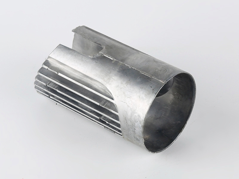
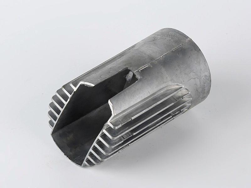
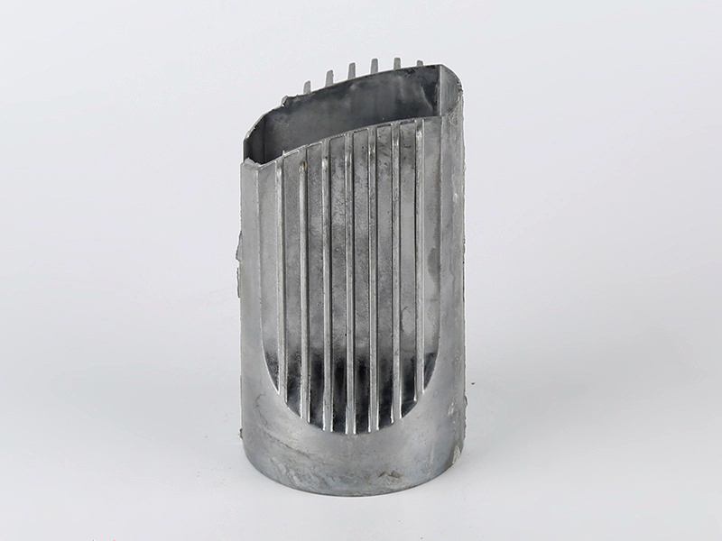
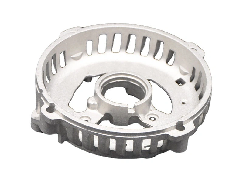
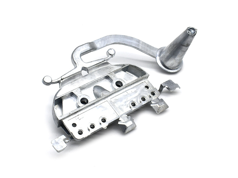
The ten defect families most often investigated in metal casting projects are gas porosity, shrinkage porosity, incomplete fill, cold shuts, oxide films and inclusions, hot tears, cold cracks, dimensional distortion, surface and mold-interface defects, and machining-exposed discontinuities. The useful question is not which name appears most often. It is which mechanism created the indication on this alloy, geometry, casting route and process lot.
Correct diagnosis requires three links: morphology and location, the stage at which the defect formed, and evidence that separates it from look-alike mechanisms. A rounded pore near an HPDC gate, an interdendritic cavity in a heavy sand casting and a hole opened by machining may all be called porosity, yet their corrective actions differ. Contain suspect product first, preserve samples and process records, then change the process only after the mechanism is supported.

A discontinuity becomes a rejectable defect when it violates a drawing, material specification, visual standard or functional acceptance criterion. Not every pore has the same consequence. A subsurface void outside a loaded or machined zone may be acceptable under one contract, while a smaller indication crossing a sealing wall may fail another. The acceptance boundary must identify feature, size or severity, method and sampling.
Do not use "defect-free" or "no porosity" as an uncontrolled purchasing phrase. Define pressure leakage, radiographic acceptance, section quality, appearance, fatigue evidence or another measurable requirement. The engineering review should connect that requirement to the likely failure mode and available process capability before tooling is released.
Contain and map: identify affected part, cavity, tool revision, machine, material lot, shift and time window. Segregate product without destroying the traceability needed for diagnosis.
Describe, do not label: record shape, size, orientation, surface character, depth and location relative to gate, riser, core, thick section, ejector and machined face.
Compare good and bad: retain parts from the same lot and a known acceptable baseline. Compare process traces, melt records, tool condition and inspection images.
Choose discriminating tests: section, polish, etch, radiograph, scan, penetrate, pressure-test or analyze chemistry only when the result can separate candidate causes.
Change one causal system: modify gating, feeding, venting, thermal balance, melt handling, geometry or handling according to the supported mechanism. Confirm the change on representative production.
A defect catalogue can help name candidates, but photographs alone rarely prove root cause. Lighting and section direction change appearance; polishing can smear soft metal across a pore; machining can connect several small voids. Preserve unaltered parts and document every preparation step.
Defect family | Typical clue | Strong confirming evidence | Primary system to review |
|---|---|---|---|
Gas porosity | Rounded, smooth voids; often linked to fill or dissolved gas | Location map plus sections and fill/vent evidence | Melt, shot, venting and vacuum |
Shrinkage porosity | Irregular or dendritic cavities in last-to-freeze zones | Thermal map, section morphology and feeding path | Geometry, feeding and thermal balance |
Incomplete fill | Missing edge or thin feature with rounded frozen front | Short-shot sequence and temperature/flow trace | Fluidity, fill time, gates and venting |
Cold shut | Seam where flow fronts met without metallurgical union | Section across seam and fill pattern | Flow-front temperature and oxide disruption |
Oxide or inclusion | Film, folded skin or foreign particle | Metallography and compositional analysis | Melt cleanliness, transfer and turbulence |
Hot tear | Irregular crack formed during constrained solidification | Crack path, thermal model and constraint review | Alloy freezing range, geometry and mold restraint |
Cold crack | Sharper fracture after solidification or handling | Fractography, timing and residual-stress evidence | Cooling, ejection, straightening and heat treatment |
Distortion | Warp, twist, mismatch or unstable datum relationship | Stage-by-stage dimensional study | Tool geometry, cooling, restraint and machining |
Surface/interface defect | Penetration, scab, solder, erosion, blister or rough patch | Surface replica/section and mold-condition record | Mold media, coating, die condition and release |
Machining-exposed discontinuity | Pore, film or hard particle appears after stock removal | Depth map tied to casting flow and machining setup | Casting soundness, stock and feature location |
Gas porosity is a void produced when gas is trapped or comes out of solution as metal solidifies. In high-pressure aluminum die casting, rounded pores may follow air entrained during rapid filling, vaporized lubricant or ineffective venting. In aluminum sand or gravity casting, dissolved hydrogen and turbulent transfer can contribute. Different processes therefore need different evidence.
Map pores by cavity and location. Gas concentrated beyond a final fill front suggests a different problem from distributed fine pores associated with melt condition. Review melt treatment, hold time, transfer, shot profile, vent condition, vacuum trace and lubricant application as applicable. Radiography can locate volumetric indications; sections show shape and relation to microstructure. Neither method alone identifies the gas source.
Correct the supported cause: improve melt handling and degassing where dissolved gas is demonstrated; reduce free-fall and folded flow; restore vent area; control spray and drying; or revise the HPDC fill profile and overflow layout. Vacuum assistance can reduce cavity gas when the die seals and evacuation path work, but a machine vacuum reading is not proof that a critical machined face is pore-free.
Shrinkage forms when a region contracts during solidification without enough liquid metal feeding it. The cavity is often irregular, dendritic or sponge-like and tends to appear in thermal hot spots: heavy bosses, junctions, isolated pads or regions cut off from a riser or pressure feed. It is not corrected by degassing.
Overlay defect locations on section thickness and a solidification study. In sand and gravity casting, review riser connection, feeding distance, chills, insulating sleeves and mold temperature. In pressure die casting, examine local intensification, gate freeze, squeeze-pin opportunity and die thermal balance. A cavity repeatedly centered in the same heavy junction is strong evidence of local feeding failure.
Redesigning the section is often more reliable than enlarging a feeder indefinitely. Core out mass, smooth thickness transitions or move a boss so it does not create an isolated liquid pocket. Then confirm the revised thermal sequence with sections or nondestructive inspection at the same locations used for the baseline.
An incomplete fill occurs when metal freezes or loses driving force before the cavity is full. The unfilled boundary often has a rounded frozen edge. Thin remote fins, long flow lengths, cold molds, inadequate metal head or pressure, blocked vents and interrupted pouring can all contribute. The remedy is not automatically to increase metal temperature.
Confirm fill sequence with short shots, simulation or instrumented trials where available. Check actual metal and mold temperature at the relevant time, not only setpoints. Review gate area, fill distance, vent backpressure, alloy fluidity, transfer delay and oxide buildup. A thin feature outside realistic process capability may require a design change.
Raising temperature can improve fluidity but may increase oxidation, die soldering, gas pickup, cycle time or grain changes. Adjust temperature only within the qualified alloy and process window. Prefer a balanced correction that shortens the path, improves venting and maintains adequate flow-front temperature.
A cold shut is a seam where two metal streams meet but do not fuse into a continuous metallic section. It may look like a line, wrinkle or lap and can be confused with a crack or surface scratch. Oxide skins on the streams, low flow-front temperature, poor meeting angle and interrupted flow all affect formation.
Section across the line. A cold shut follows the meeting interface and may contain oxide; a later crack has a different fracture path and opening history. Compare the seam with predicted or observed flow-front convergence. Check whether it tracks a gate change, blocked vent, low shot performance or mold-temperature imbalance.
Correct the fill pattern rather than polishing away the visible line. Move or resize gates, change sequencing, stabilize tool temperature, reduce pauses and provide an overflow where the meeting front carries contaminated metal. If the seam lies in a loaded or sealing wall, define internal acceptance and functional validation after the process change.
Oxide films form at an exposed melt surface and can fold into the casting during turbulent transfer or filling. Slag, refractory, sand, flux residue and intermetallic particles are other inclusion sources. A dark spot or hard particle should not be assigned to "dirty metal" until composition and morphology support that conclusion.
Use polished sections, etching and microscopy; add elemental or phase analysis when source identification matters. Compare an indication with melt, furnace lining, ladle, filter, mold sand and coating materials. Folded bifilm indications may be thin and orientation-sensitive, so a radiograph can miss them.
Control source and transport. Clean and skim using the qualified melt practice, protect transfer, avoid vortexing and excessive free-fall, maintain refractory and mold integrity, and use filters only with a gating design that fills them correctly. Filtration cannot compensate for erosion downstream of the filter.

Hot tears form near the end of solidification when a weak semisolid region is strained but cannot feed or accommodate contraction. They often follow hot spots, sharp re-entrant corners, abrupt section changes or regions restrained by a core or mold. The surface is commonly irregular and oxidized because the crack formed at high temperature.
Review alloy freezing behavior, crack location, thermal gradient and restraint together. A crack at the same junction across lots points toward geometry and solidification, while a sporadic crack after rough handling may be cold damage. Section the crack tip and inspect its relation to grain boundaries and last-to-freeze structure.
Reduce restraint and thermal concentration: add radii, balance sections, improve core or mold collapsibility, revise feeding and cooling, and review ejection timing. Alloy change may alter susceptibility but affects castability and properties, so it needs design approval and repeat qualification.
Cold cracks occur after the casting has largely solidified. Residual stress, uneven cooling, premature ejection, forceful gate removal, straightening, heat treatment, machining or impact can initiate them. Their sharper fracture surface and timing distinguish them from hot tears, although an opened hot tear can later resemble a cold crack.
Establish the first process stage where the crack is visible. Inspect before and after ejection, trim, heat treatment, blasting and machining. Penetrant or magnetic-particle examination may reveal surface-breaking cracks on compatible materials; fractography and metallography help identify origin and propagation.
Correct the stage that creates stress or overload. Balance cooling, support the part during ejection, revise trim and fixture forces, control heat-up and quench, or remove a notch. Do not weld, blend or impregnate a crack unless the governing specification explicitly allows an approved repair and reinspection.
Dimensional defects include mold or die mismatch, core shift, flash-related closure, shrinkage variation, warp, twist and unstable datum relationships. Measurement can also create a false signal when the part is hot, constrained differently or referenced from an inconsistent datum. Start by validating the measurement system.
Measure at release from the mold, after trim, after aging or heat treatment, after blasting, after machining and after coating when those stages can move the part. A stage-by-stage study shows whether geometry is born wrong in the tool or moves later. Separate cavity, tool-temperature and time trends.
Correct tooling or core location when the mean is wrong; correct thermal balance, restraint or process variation when spread is excessive. Machining cannot economically recover a casting that lacks stock on one side. The machining plan should share a datum strategy with casting inspection.
This family includes sand penetration, scabs, buckles, erosion, burn-on, metal penetration, die soldering, drag marks, blisters, flow marks and excessive roughness. The mechanism depends strongly on process. A rough sand-cast patch may originate in mold media; an HPDC drag mark may follow inadequate draft, local die pickup or ejection misalignment.
Record the defect on an uncleaned part and its exact tool location. Compare mold sand, coating, compaction, moisture and pouring conditions for sand castings. For permanent dies, inspect surface condition, release application, local temperature, alloy attack, vent residue and ejection. Section blisters to determine whether subsurface gas expanded during later heat exposure.
Finishing should not become routine defect concealment. Blasting changes texture but does not restore a cold shut. Polishing can open pores. Coating may bridge a small depression yet later blister over contamination. Define substrate acceptance before cosmetic finishing.
A part may look sound as cast and reveal pores, shrinkage, films, inclusions or hard spots when machining removes the skin. The indication is not necessarily caused by machining; the operation exposes a depth and location that were previously hidden. It can also connect isolated voids into a leak path.
Map defect depth, tool path and fixture location against gates, overflows, risers and thermal hot spots. Compare roughing and finishing stages. Analyze hard particles before changing cutting tools. For pressure components, perform the specified leak test after final stock removal and cleaning, because an as-cast test may not represent the delivered wall.
Correct the casting mechanism and the design relationship. Move a machined face away from a risky last-fill or hot-spot zone, reduce unnecessary stock, revise local feeding or venting, and use a representative trial. The supplier and buyer must agree whether impregnation is permitted, what it repairs and how it is documented.

No inspection method finds every defect. Visual inspection detects accessible surface conditions. Penetrant reveals surface-breaking discontinuities on suitable nonporous surfaces. Magnetic-particle inspection applies to ferromagnetic material. Radiography is sensitive to volumetric density differences but less reliable for thin films aligned with the beam. Ultrasonic response depends on material structure, geometry and reference standards. Computed tomography can map complex indications but still needs validated resolution and acceptance.
Destructive sections and metallography are powerful for diagnosis because they reveal morphology and microstructure, but they sample only the cut location. Pressure and functional tests answer a defined product question without necessarily naming the defect. Use the available inspection equipment with written method, calibration, location, sensitivity and acceptance.
Sampling must follow consequence and process knowledge. A first article can validate design and tool assumptions; it cannot establish every future lot. Production monitoring should include variables linked to the known mechanism and a reaction plan. When a trend moves, contain product from the last verified point.
A useful corrective-action report states the defect requirement, affected population, containment, morphology, candidate causes, tests performed, confirmed mechanism, action, validation and ongoing control. "Operator retrained" is insufficient when the system allowed the wrong condition without detection. Update work instructions, tooling, alarms, maintenance or control plans according to the cause.
Simulation supports hypotheses for filling and solidification, but it inherits assumptions about material, boundary conditions, heat transfer and venting. Correlate the model with short shots, temperature measurements, sections and actual defect locations. A colorful result is not validation by itself.
Track recurrence by defect family, feature, cavity and stage, not only total scrap. A reduced reject count can hide movement from casting scrap to machining or finishing. Include rework, destructive testing and customer returns in the same quality boundary.
Defect prevention has commercial consequences. More cavities, a faster cycle or less machining stock may lower quoted cost while narrowing the process window. Extra radiography can increase sorting without removing root cause. Compare the prevention action, inspection cost and consequence of escape in the same decision.
Agree who pays for qualification sections, destructive tests, rework development, tooling correction and product held during investigation. Define concession authority and expiry. A temporary acceptance on noncritical samples should not silently become the production standard.
For uncertain geometry, a low-volume validation route can test specific risks, but only production-representative tooling proves production fill and thermal behavior. Use the project cost model to compare prevention, inspection and failure exposure rather than chasing a nominal zero-defect claim.
Provide controlled CAD and drawing, alloy and material condition, selected or permitted casting process, annual and release demand, critical zones, machined stock and final wall, pressure or load cases, cosmetic surfaces, finish, assembly, service environment, prohibited repairs, inspection methods, acceptance criteria, sampling, certificates and traceability. Mark whether the requirement applies as cast or after all secondary operations.
Ask the casting supplier for its proposed gating, feeding, venting, thermal and melt-control approach; risk review by feature; trial and section plan; measurement method; production variables; reaction plan; subcontracted inspection; repair policy; change control; and exclusions. Compare suppliers on how they close the part's specific risks, not on an unsupported claim of defect-free production.
Why do my die-cast aluminum parts appear uneven or dark after anodizing?
Is the corrosion resistance of anodized magnesium alloys sufficient for everyday use?
Are the colors of anodized titanium alloys stable, or will they fade over time?
Can Newway assist us in testing and selecting the most suitable aluminum alloy grade for anodizing?