Why do my die-cast aluminum parts appear uneven or dark after anodizing?
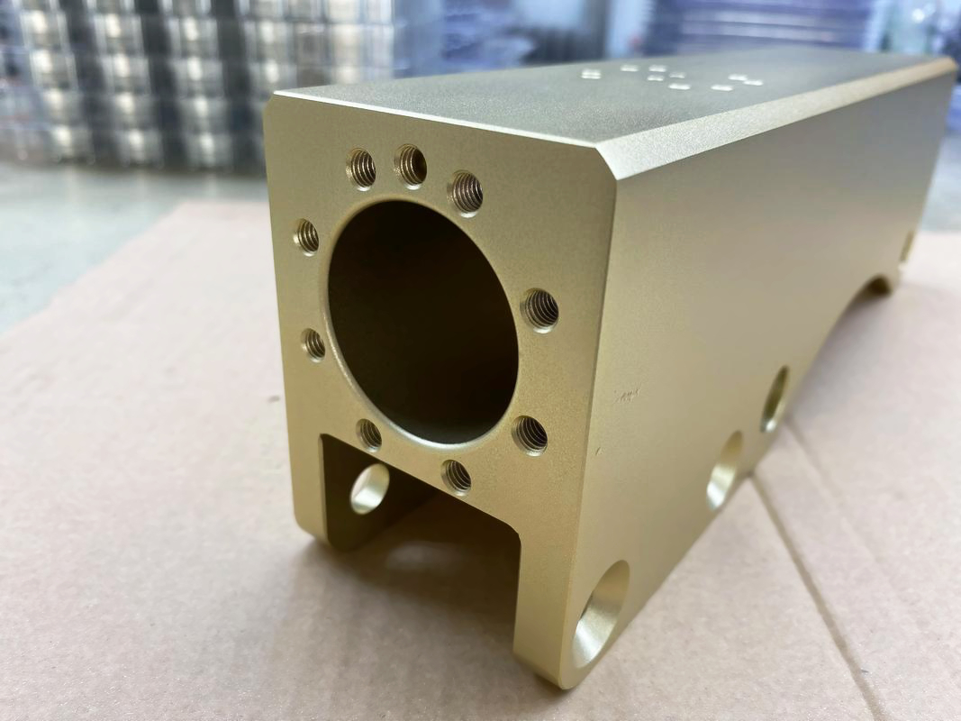
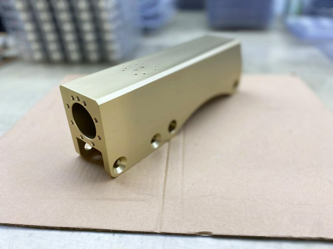
Die-cast aluminum often looks dark or uneven after anodizing because its surface is a mixture of aluminum matrix, silicon particles, intermetallic phases and casting defects rather than a uniform wrought structure. The aluminum converts to oxide, while the other constituents dissolve or oxidize differently and change how the surface reflects light. Flow lines, dense casting skin, exposed pores, machining transitions and inconsistent cleaning can add patches or streaks. Process adjustment may reduce variation, but it cannot make a high-silicon pressure casting look identical to anodized wrought aluminum.
The alloy creates the baseline appearance
Pressure-die-casting alloys are chosen to fill the die and solidify reliably. In a grade such as A383/ADC12, silicon supports casting behavior but does not form the same transparent anodic film as the aluminum matrix. The resulting silicon-rich relief and residual constituent particles scatter and absorb light, often producing a gray cast, dark speckling or lower color saturation. Copper-, iron- and manganese-bearing intermetallics can add local contrast after etching and desmutting.
Composition ranges in a material standard are not a promise of identical color from every melt. Chemistry within the allowable range, recycled-metal control, melt cleanliness and local solidification can change the constituent population seen at the surface. If appearance matters, require material traceability and compare actual production lots. Bare parts that look alike can separate visibly only after pretreatment reveals their microstructure.
Casting flow and porosity add a second pattern
In high-pressure aluminum die casting, metal fronts meet, skin forms against the die, and different regions cool at different rates. Those events can leave flow marks, cold-lap boundaries, segregated bands and local surface texture. Anodizing does not create all of these patterns; it often makes existing metallurgical differences easier to see.
Open pores present another mechanism. A pore can hold cleaner, etchant or anodizing solution, then release it during a later rinse or drying stage. That may cause a spot, stain, bleed trail or local coating disruption rather than the broad gray tone caused by alloy chemistry. Blisters can indicate trapped gas, subsurface discontinuity or thermal/process effects and should not be classified as a color issue without sectioning or other evidence.
Use the symptom to direct the investigation
| Observed condition | Likely contributors | Confirmation method | Decision |
|---|---|---|---|
| Uniform gray or generally dark finish | Alloy constituents, etch response and chosen anodizing/color route | Compare known-alloy coupon and production casting through the same bath | Accept a functional appearance, revise finish target or change substrate/process |
| Mottled patches or flow-shaped bands | Solidification pattern, segregation, die condition or local pretreatment response | Compare as-cast map, cavity/shot records and parts before/after etch | Control casting window and master sample; do not promise wrought appearance |
| Dark dots with bleed trails | Open porosity retaining process solution | Microscopy, pressure/vacuum evidence where appropriate, rinse and bake study | Improve casting/cleaning route or choose an opaque barrier finish |
| Sharp boundary at machined area | Cast skin versus exposed interior, roughness or coolant residue | Surface roughness, cleaning audit and matched machined coupon | Define texture and pretreatment by surface zone |
| Random fingerprints, islands or contact shadows | Handling contamination, incomplete cleaning, rack contact or poor solution access | Water-break/cleanliness check, rack map and repeat trial | Correct handling, racking and pretreatment controls |
Machining and blasting change the visual base, not the alloy
Machining can remove a damaged surface and create controlled roughness, but it also removes the dense casting skin and may expose pores or different microstructure below it. A cosmetic face produced by CNC machining should be tested in its production feed, tool and coolant condition. A polished prototype cut from wrought plate is not representative of a machined die casting.
Fine abrasive preparation can reduce gloss and blend shallow visual variation. It cannot remove silicon from the alloy or repair cold laps and pores. Sand blasting also changes roughness, edge definition and the area available for soil retention. Specify media, coverage and protected surfaces, then approve the blasted-and-anodized combination rather than either operation alone.
Pretreatment can amplify or soften contrast
Cleaning must remove die lubricant, machining fluid, polishing compound and handling soil. If cleaning is incomplete, those residues block uniform reaction. Etching then alters roughness and preferentially attacks phases at different rates. Desmutting removes residual constituent material, but its chemistry and time must fit the alloy. Too little action leaves contamination; an aggressive route may increase texture or dimensional change. The processor should qualify a window on the actual alloy instead of importing a wrought-aluminum recipe.
Racking matters as well. Electrical contact influences current flow and leaves an uncoated contact mark. Part orientation controls drainage and gas release. Deep pockets can receive different agitation and rinsing from exposed faces. Map rack points outside cosmetic and sealing zones, and review whether all surfaces can drain.
Decide whether the requirement is visual or functional
A dark film is not automatically a failed film. If the requirement is corrosion protection, electrical insulation or a wear-related property, inspect the specified functional characteristic at agreed locations. If the requirement is a brand color, those same test results do not excuse mottling. Use a signed master sample and a controlled visual method for appearance, plus separate drawing criteria for film, sealing and final dimensions.
When opaque, uniform color is more important than showing the metal, paint or powder may be a better route. That decision still needs adhesion, pretreatment, edge coverage and environmental validation. A coating can hide visual variation but cannot turn structural porosity or a cold shut into acceptable metal.
Run a trial that can isolate the cause
Process several production-intent parts together with a known-material coupon. Photograph and map each part before cleaning, after mechanical preparation, after etch/desmut and after anodizing. Keep alloy lot, casting cavity, shot or batch identity, machining route, rack position and bath lot traceable. If only the casting shows a flow-shaped pattern, substrate structure is implicated. If both coupon and casting fail in the same way, the common pretreatment or anodizing conditions deserve attention.
For the RFQ, provide the exact alloy and casting process, drawing, cosmetic zones, as-cast versus machined faces, target texture and color, accepted master, service exposure, film/test requirement, annual volume and allowed repair. Ask the supplier to state the expected visual limitation before tooling approval. The technically sound outcome may be a controlled gray functional finish, an opaque coating, a different alloy/product form, or a redesign that moves the cosmetic face away from the pressure casting. Evidence from the actual part should choose among them.