Die Mold Machining for Casting Tools: Datum Control, Cooling and Trial Evidence
Die mold machining for casting tools is the controlled manufacture of cavity, core, insert, parting, cooling, and moving-tool features that determine how a casting is formed and released. It is different from machining a finished production part. The toolmaker is creating the surfaces that will later create the casting, so a small error in a cavity, insert, slide, or parting interface can appear as a dimensional shift, flash, mismatch, distortion, or repeated surface defect on every part.
The correct machining plan begins with the alloy, casting process, part geometry, production quantity, and downstream machining. Tool and die making should include datum strategy, cavity and core inspection, cooling and moving-element checks, tryout, correction, and the records needed for repeat production. A buyer should not compare tool quotes on machining hours alone. The useful question is whether the machining and trial route will prove the functional features of the finished casting.
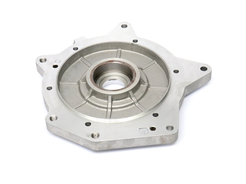
Tool Machining Starts With a Datum Plan
A casting tool has several coordinate relationships: cavity to core, cavity to parting surface, insert to base, slide to cavity, cooling feature to working surface, and the tool coordinate system to the part drawing. If those relationships are not controlled, the tool can be dimensionally accurate in isolated areas and still create a part that fails in assembly. The supplier should identify the tool datums and show how they relate to the functional datums on the part.
Do not assume the parting surface is automatically the best reference for every tool feature. A parting face may be stable for one operation and not for another. A cavity insert may need a dedicated locating surface. A slide may require a fitted guide and a controlled shutoff. The correct datum is the one that preserves the functional relationship through machining, assembly, tryout, and repair.
For complex tools, record the datum scheme in the tool drawing and inspection report. If a cavity is repaired or an insert is replaced, the same scheme should be available to reproduce the relationship. This is more useful than a generic statement that the tool was machined on a precision machine.
Tool relationship | Failure if it moves | Evidence to request |
|---|---|---|
Cavity to core | Wall shift, bore position error, or uneven section | Tool measurement and representative casting section or dimension check |
Insert to base | Step, mismatch, flash, or repeated surface mark | Insert fit record and parting-surface inspection |
Slide to cavity | Cross-feature misalignment, flash, or difficult release | Slide movement and shutoff check plus trial sample |
Cooling to working surface | Thermal imbalance, distortion, or unstable cycle condition | Cooling check and trial observations linked to the risk zone |
Cavity, Core, and Parting Machining
Cavity machining creates the external form, while core machining creates internal geometry. Both surfaces must include the appropriate shrinkage, draft, radii, surface condition, and allowance for finishing. A cavity may require different polishing or texture from a hidden core surface. A core may need a stable print and a venting path. The tool drawing should identify which surfaces are transferred directly to the casting and which are intended for later machining.
Parting surfaces need flatness, alignment, and a controlled shutoff. If the shutoff is poor, flash can form around a gasket land, bore, or connector opening. If a parting step is intentionally machined away, the casting and post-machining allowance must support that sequence. The toolmaker should review where flash will be trimmed and whether the trim line can be accessed without damaging the functional face.
Small radii and sharp edges are often where tool machining, polishing, and maintenance become difficult. A sharp cavity edge can wear or chip; a very small internal radius may be hard to measure and reproduce. A radius change can improve tool life and casting behavior but alter the part. Buyers should approve such changes through the drawing rather than treating them as invisible toolmaking detail.
Moving Tool Elements and Shutoffs
Slides, lifters, cores, and replaceable inserts form features that cannot be produced by a simple opening and closing movement. Each moving element requires location, guidance, clearance, lubrication, travel, and a shutoff that contains the metal during filling. The tool machining plan should inspect both the static fit and the movement under the thermal and production conditions that can be represented.
A slide that forms a connector opening may also create a parting line around the opening. A core that forms a bore may shift under injection or clamping force. A replaceable insert may make repair easier but introduce a joint that must be controlled. The buyer should ask which surfaces are replaceable, how they are registered, and how a replacement is qualified.
Do not measure a slide only in its parked position. Check movement, end position, shutoff contact, and access for cleaning or maintenance. A small burr or wear point can create flash that appears intermittently. If the feature is machined in the casting later, inspect its location against the part datum and not only against the tool coordinate system.
Cooling and Thermal Machining Decisions
Cooling passages are machined into or assembled around the tool to control heat. Their position and integrity affect the cavity surface, the cycle, and the balance between heavy and thin sections. A cooling channel that is too close to a working surface may weaken the insert or create an unwanted thermal pattern. A channel that is too far away may not remove heat from a boss, rib intersection, or last-fill region.
The supplier should define how cooling passages are checked for continuity, leakage, blockage, and connection. The exact test depends on the tool and equipment, but an undocumented channel is difficult to maintain. Record fittings, plugs, inserts, and changes to the cooling layout. If a channel is modified after a trial, review the linked casting characteristics.
Thermal issues can look like dimensional or material issues. A cavity may produce a part that is stable after the tool reaches temperature and different during the first shots. A local hot spot can change distortion or surface condition. Tool trials should therefore include warm-up behavior and observations from the risk zones, not only one cold measurement of the tool steel.
Cooling concern | Part symptom | Tool-machining or trial response |
|---|---|---|
Blocked or leaking passage | Unstable temperature or reduced cooling | Check passage integrity and record the correction |
Channel too close to surface | Local texture, hot spot, or insert weakness | Review wall around channel and replacement strategy |
Uneven circuit balance | Distortion, cycle variation, or dimensional movement | Compare tool layout with trial measurements and part map |
Unrecorded modification | Repeat order behaves differently from the approved sample | Update tool drawing, maintenance record, and approval status |
Machining, Finish, and Measurement of Tool Surfaces
Rough machining establishes the cavity, core, insert, and base geometry. Finishing operations refine shutoffs, polish, texture, radii, and surfaces that transfer directly to the casting. The appropriate finish depends on alloy, part surface, release behavior, cosmetic requirement, and whether the casting is later machined or coated. A mirror finish is not automatically correct for every cavity.
Measurement should prioritize the features that control the finished part. Inspect cavity-to-core relationships, parting surfaces, shutoffs, slide positions, insert fits, critical radii, and tool features that locate the casting in downstream machining. Use the same reference logic as the part drawing where practical. A tool inspection report full of isolated coordinates may still miss the relationship between a bore-forming core and a mounting face.
Surface texture should be approved with a clear reference. If the casting is cosmetic, a visual sample can be useful alongside tool-surface inspection. If the face is machined, the as-cast texture may matter only for stock and defect exposure. The finish requirement should state the visible zone and the intended downstream process.
Tryout Turns Tool Machining Into Part Evidence
Tool machining is not complete when the cavity passes an inspection report. Tryout shows how the tool, alloy, machine, process, and part interact. Review fill, flash, parting mismatch, gate and overflow trim, ejector marks, surface transfer, distortion, and the condition of the critical sections. Take measurements before and after machining when the casting is intended to become a finished component.
A trial sample should be made under documented conditions and identified by tool revision. If the part is pressure-sensitive, inspect or test the pressure boundary. If it contains a bearing bore or sealing land, use the intended fixture and machining route. If a coating is required, verify that the casting surface and masking plan are compatible before approving the visual result.
Corrections should be linked to a cause. Removing steel from a cavity may change wall thickness, draft, or machining allowance. Moving a gate may change a cosmetic mark and the last-fill region. Adjusting a slide may improve flash and change a cross-feature position. Record the correction and recheck the characteristics it can affect. This is the bridge between a tool trial and a reliable production release.
Tool Maintenance and Repairability
Die mold machining should anticipate maintenance. Wear surfaces, gate areas, shutoffs, slides, ejector holes, and high-heat inserts may need inspection or repair. A replaceable insert can reduce the consequence of local damage, but its joint and location must be controlled. A repair that changes a cavity radius or parting line may change the casting and should be approved when it affects function or appearance.
Maintain a tool history that identifies the date, area, reason, action, and post-repair check. Track flash, dimensional drift, surface marks, sticking, cooling issues, and repeated trim defects. The maintenance record helps distinguish normal wear from an unstable process. It also protects the buyer when the same tool is used after a long storage period or at a different machine.
Ask who owns the tool records, who approves repairs, what spare inserts are supplied, and how a replacement is matched to the original. These commercial decisions affect repeat production and should be included in the tooling scope rather than left to an informal conversation after the tool is accepted.
RFQ Inputs for Die Mold Machining
Provide the controlled part drawing, 3D model, alloy, process, volume, machine envelope, parting and draft requirements, visible surfaces, machined features, critical datums, pressure or load boundaries, finish, inspection, and expected trial condition. State whether the request covers die design, rough and finish machining, polishing or texturing, cooling, moving elements, tryout, correction, maintenance, and documentation.
Ask the supplier to show tool datums, cavity and core strategy, gates and vents, slides or cores, cooling, ejectors, inspection points, and trial acceptance. Require a written boundary for changes caused by customer drawing revisions, and identify who controls tool ownership, storage, maintenance, and repair.
Neway's tooling route should be compared on the evidence it produces for the finished part, not only on the number of machining operations. Include post-machining in the discussion when the casting's as-cast condition must be converted into a precision interface.
Datum Control Is the Core of Die Mold Machining
Die mold machining begins with a datum strategy that survives design, roughing, heat treatment, finishing, assembly, and measurement. A cavity dimension is not useful if the cavity is positioned from a reference that disappears during the next operation. The tool drawing should identify the base, locating surfaces, insert seats, parting faces, and inspection datums. Those references allow the toolmaker to relate a machined pocket to the die assembly and ultimately to the casting drawing.
Roughing and finishing also have different jobs. Roughing removes stock while leaving a stable condition for later operations; finishing establishes the cavity, shutoff, and parting surfaces that affect the casting. The process plan should protect thin ribs, sharp detail, deep pockets, and corners where a cutter cannot reach directly. A design may need electrodes, smaller tools, inserts, or a change to the part geometry. The buyer should learn about those constraints while the tool is still open for design changes.
Cooling, Venting, and Accessibility Must Be Machined Into the Tool
Cooling passages influence die temperature, cycle stability, and the way a casting shrinks as it leaves the cavity. Their location must be coordinated with cavity depth, inserts, slides, ejectors, and fasteners. A passage that is easy to drill may still cool the wrong region or weaken a thin section of the tool. The machining plan should identify plugs, connections, inspection access, and the possibility of cleaning or repair. The same review applies to vents and overflows: their land, depth, discharge, and trimming access affect both toolmaking and casting quality.
Accessibility is often missed in a first tool model. If a cavity insert cannot be removed without dismantling several assemblies, a simple repair becomes expensive and slow. If a vent is hidden behind a slide, cleaning may be inconsistent. If an ejector pocket cannot be measured after assembly, a change may go unnoticed. A robust tool plan is not a slogan; it is a set of physical access decisions recorded in the design and maintenance scope.
Trial Evidence Must Include the Tool and the Part
A die mold machining review should continue through the first casting trial. Inspect the parting surfaces, shutoffs, cavity detail, insert steps, gate and overflow edges, cooling connections, ejector marks, and slide interfaces. On the casting, check flash, mismatch, fill of remote features, distortion after ejection, and the relationship between cast datums and machined interfaces. If the first sample requires a tool correction, record the affected tool surface, revision, reason, and reinspection method.
Tool acceptance should also separate visual workmanship from functional performance. A polished cavity may look acceptable while a core or slide is out of position. A dimensionally correct insert may still create flash if the shutoff is not loaded correctly. The buyer should ask for assembly checks, cavity or insert identification, tool inspection records, and a trial report tied to the approved drawing. This makes later maintenance easier to interpret.
RFQ Inputs for a Machined Casting Tool
Include the casting alloy and process, part model and drawing, cosmetic faces, functional surfaces, expected volume, tool life assumptions, cycle or maintenance expectations, cooling and vent requirements, machining datums, inspection method, and ownership terms. Ask what is included in design, programming, electrodes, heat treatment, assembly, trial, corrections, spare inserts, and storage. Neway's tool and die making route can be reviewed with the casting scope when the buyer needs one controlled chain from tool model to finished part.
Measure the Tool Where the Casting Uses It
A tool measurement is useful when it explains a casting feature. Check cavity-to-cavity position, shutoff closure, insert steps, gate and vent geometry, ejector locations, and cooling connections against the tool and part datums. If a tool surface is changed after a trial, recheck the affected part feature rather than assuming the repair is neutral.
This relationship is especially important for a machined face or bore. The tool may produce a nominal surface while the raw casting moves during release. Neway's toolmaking route can be reviewed with the casting and machining inspection plan.
Buyer Summary
Die mold machining controls the cavity, core, parting, cooling, moving elements, and tool relationships that create a repeatable casting. The buyer should require a datum plan, functional tool inspection, production-representative tryout, correction records, and a maintenance strategy.
A tool quotation becomes commercially useful when it explains how the machined die will prove the part's geometry, machining, finish, and inspection requirements. That is the standard for comparing die mold machining services without mistaking a machine specification for casting quality.
FAQ