How Does Die Mold Machining Affect Maintenance?
Die mold machining affects maintenance by determining which surfaces wear, which components can be accessed or replaced, how cooling and venting are serviced, and how repairs can be measured back to the original datum system. A tool that produces a good first sample can still become expensive to operate if a worn shutoff is difficult to reach, a cooling passage cannot be cleaned, or a repair changes the cavity without a controlled recheck.
Maintenance planning begins during tool design. Mark wear-prone edges, slides, inserts, ejector bores, parting surfaces, cooling connections, vent areas, and surfaces that are likely to be repaired. State whether the component is replaceable, weld-repairable, polishable, or intended to be protected from routine work. The correct boundary depends on alloy, process, volume, cycle condition, surface requirement, and the consequence of a change.
Machined Features That Need a Plan
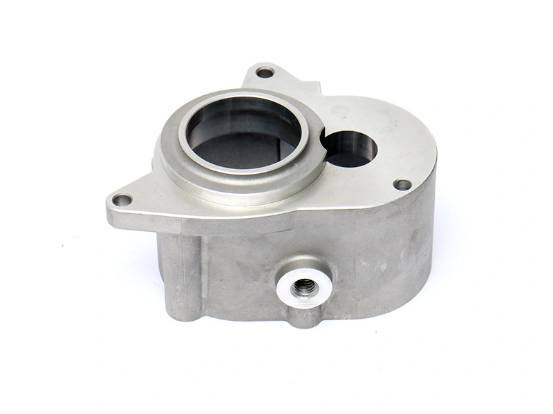
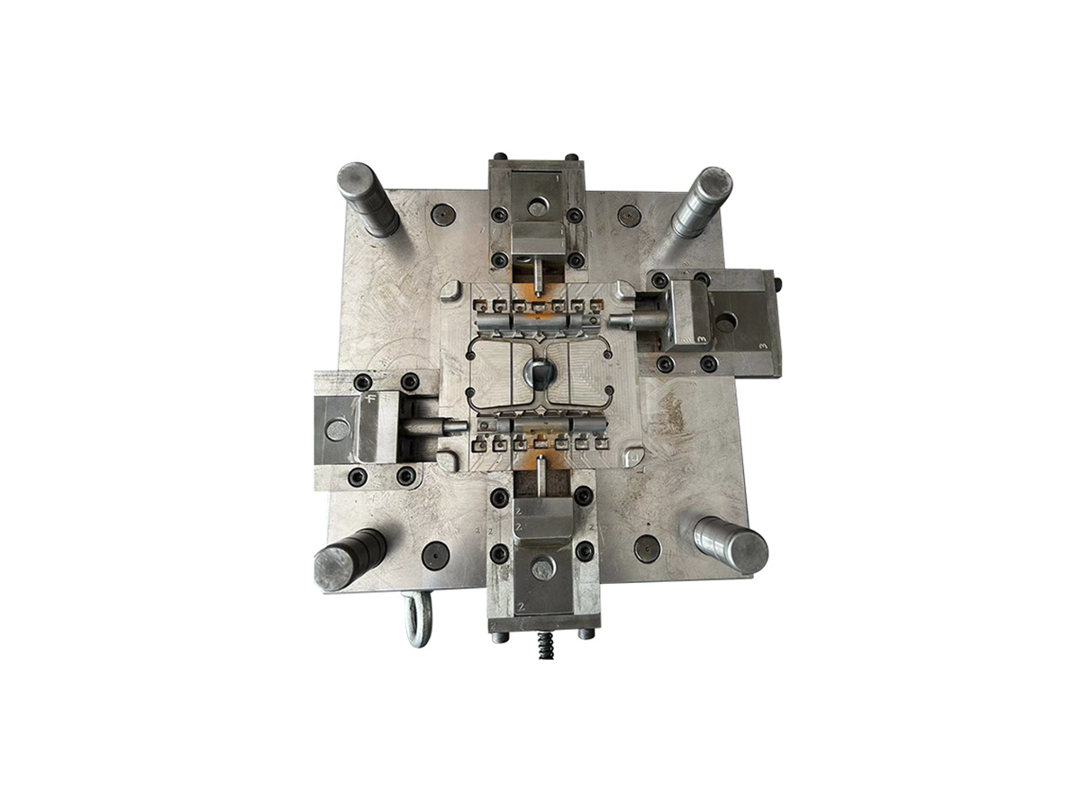
Parting and shutoff surfaces can develop flash as alignment or contact changes. Slides and lifters can wear at guides, locks, or sealing edges. Inserts may protect a concentrated wear area but require repeatable seating and replacement inspection. Ejector bores can affect release if they become damaged or misaligned. Cooling passages can lose flow because of scale, debris, plugs, or a leaking connection.
The maintenance plan should describe the symptom, likely cause, access route, measurement, repair limit, and release check. Do not rely on polishing a surface until flash disappears if the polishing changes the functional geometry or parting alignment. A local repair may require a casting trial and a finished-part measurement rather than a visual sign-off.
Inserts and Datums Support Repeatable Repair
Replaceable inserts can shorten a repair or isolate the area that wears most quickly. Their benefit depends on the joint, locating surfaces, fasteners, cooling, surface finish, and the ability to install them without shifting the cavity. The tool drawing should identify the insert datum and the features it controls. After replacement, inspect the assembled tool and the affected casting features.
Keeping the original datum system is important. If a repair is measured from an improvised surface, the tool may return to production with an unrecorded shift. The casting should be checked relative to the same functional relationships used for the initial approval. The tool and die making route should include the repair record and requalification boundary.
Maintenance area | Machining-related risk | Control |
|---|---|---|
Parting or shutoff | Flash, mismatch, or altered part geometry after polishing or repair | Datum-based contact check, assembled inspection, and affected-feature sample |
Slide or lifter | Wear changes movement, home position, or side feature | Movement check, wear limit, replacement fit, and casting verification |
Insert | Joint witness, seating shift, or wrong cavity relation | Insert datum, seating inspection, surface check, and trial evidence |
Cooling circuit | Blocked, leaking, or inaccessible passage | Flow or pressure check, cleaning access, circuit record, and repair log |
Maintenance Must Follow the Part Risk
A hidden cosmetic witness may have a different maintenance limit from a change at a gasket land, bearing bore, pressure passage, or mounting datum. Define the consequence of flash, mismatch, dimension shift, surface damage, or distortion. A visual check may suit an appearance edge, while a functional feature needs dimensional, assembly, leak, or other specified evidence.
When machining or repair changes the tool, review the casting and downstream post-machining condition. A repaired cavity can alter stock or fixture support even if the nominal tool dimension is restored. Keep the old and new conditions linked to the effective production lot.
The Practical Maintenance Answer
Die mold machining supports maintenance when it creates accessible wear boundaries, repeatable inserts, serviceable cooling and venting, and datums that survive repair. Approve maintenance work with the affected casting features and finished-part requirements, not only with a tool-room visual check. The tool remains reliable when its geometry, service history, and part evidence stay connected.
Maintenance Boundaries in the Tool Model
Define wear boundaries where a repair can be isolated without disturbing the rest of the cavity. Replaceable inserts, slide shutoffs, vent lands, ejector bores, and cooling plugs should have identification and access that a maintenance technician can use after the tool is assembled. Record the fit, orientation, and locating surfaces so a replacement does not depend on visual judgment alone.
Maintenance inspection should follow the feature that matters on the casting. Check a shutoff through flash and mismatch at the parting interface; check a worn cavity detail through the affected dimension or surface; and check a cooling circuit through access, flow, leakage, or the thermal symptom it controls. A tool-room measurement is useful only when it explains a part result.
Keep repair history with the effective part and lot. Note the removed material, replacement insert, tool revision, trial sample, and downstream reinspection. This makes it possible to distinguish normal tool wear from a process change and to decide when an old casting approval no longer applies.