What Is a Die in Casting? Tool Components, Parting Lines and RFQ Decisions
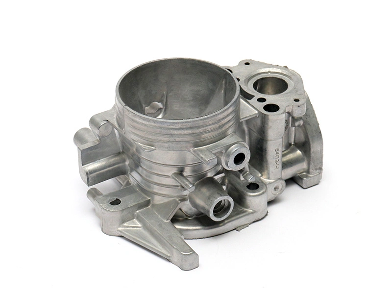
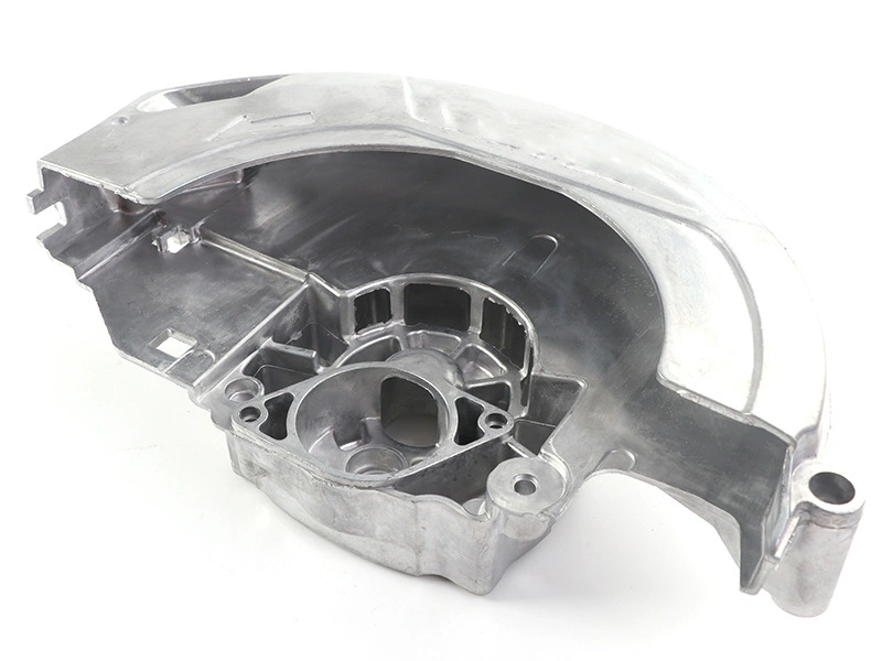
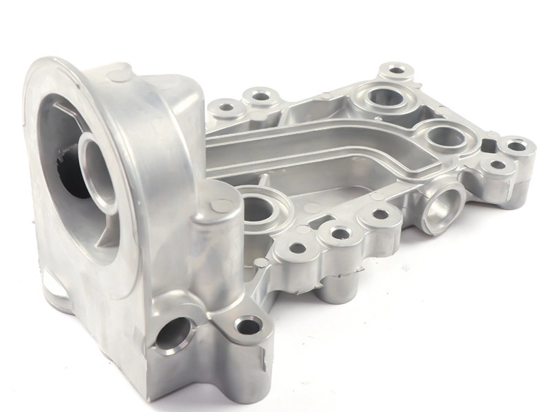
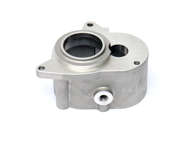
A die in casting is the reusable metal tool that contains the cavity into which molten metal is introduced to form a repeatable part. It is more than a hollow negative of the component. A production die includes cavity and core surfaces, a parting line, gates and runners, vents or overflows, cooling passages, ejectors, slides or other moving elements, and replaceable inserts where wear or repair risk is concentrated. For a buyer, understanding what a die does makes it easier to review a quotation, identify tooling risks, and decide which part features should be cast, machined, masked, or left open.
The die design must follow the alloy, casting process, part geometry, volume, surface requirement, and inspection plan. A die for an aluminum housing is not specified in the same way as a die for a zinc handle or a copper-alloy component. Tool and die making affects wear and repair decisions, but tool material alone does not determine part quality. The die must fill the cavity, release the part, control heat, protect critical surfaces, and support the downstream machining route.
Die Versus Mold and Pattern
Manufacturing language uses “die,” “mold,” “tool,” and “pattern” differently across processes. In pressure die casting, the die is normally a durable metal tool designed for repeated injection of molten alloy under controlled conditions. In sand casting, a pattern creates the cavity in molding sand and may be used with cores for internal passages. In urethane casting, a flexible or rigid mold may support prototype production. These terms are related, but a buyer should state the process rather than assume that a tooling quotation is interchangeable.
The distinction changes the cost and the design review. A reusable pressure die may require hardened inserts, slides, cooling circuits, and precise alignment. A sand-casting pattern may offer a different approach for low-volume or large geometries but leaves a different surface and dimensional condition. A prototype mold can validate fit and appearance without representing the porosity, parting, gate, or ejection behavior of a production die. The tooling name should always be read with the production route and the intended evidence.
A drawing package should identify whether the supplier is expected to design a production die, a bridge tool, a pattern, a prototype mold, or only a machining fixture. It should also identify ownership, maintenance, revision, and the point at which the tool is considered accepted. Ambiguity at this stage can lead to a low initial quotation that excludes the tool features needed to make the finished part.
Tool term | Typical role | Buyer should confirm |
|---|---|---|
Pressure die | Reusable metal cavity for repeated die casting | Alloy, machine route, cavity layout, cooling, ejection, and maintenance scope |
Sand-casting pattern | Forms the external cavity in a sand mold | Pattern material, parting, draft, cores, allowance, and expected volume |
Prototype mold | Supports early parts or limited runs for design validation | Which production characteristics it can and cannot represent |
Machining fixture | Locates a casting for drilling, milling, or finishing | Datums, support, clamp control, and relationship to functional features |
The Cavity, Core, and Parting Line
The cavity creates the external shape of the casting, while a core or core feature forms internal geometry. The parting line is where die halves or tool elements meet. Those three decisions influence flash, draft, ejection, cosmetic appearance, and machining allowance. A parting line across a sealing face can create a mismatch or require extra machining. A core that forms a narrow passage can improve function but add alignment and inspection demands.
Review the proposed parting direction with the assembly. Visible surfaces, gasket lands, connector openings, bearing seats, and precision datums should be protected from unnecessary parting mismatch when the geometry allows. If the line must cross a functional surface, define the condition and finishing route. The die review should also identify where flash will be trimmed and where the trim boundary may be visible or interfere with a mating component.
Draft is part of the release decision because the part must leave the die without scuffing, deformation, or excessive ejector force. A shallow draft may preserve an envelope but increase release risk on a deep wall. A larger draft may simplify ejection but change the wall, opening, or fit. The right value depends on process, alloy, depth, surface texture, and whether the surface is machined. The buyer should ask for a design alternative when draft and envelope are in conflict instead of requesting a fixed universal number.
Gates, Runners, Vents, and Overflows
The die includes the path that delivers molten metal to the cavity and the features that let air and excess metal leave it. Gates influence fill direction, local heat, surface marks, and the location of material that must be trimmed. Runners distribute the melt to one or more gates. Vents and overflows support air evacuation and can help manage the final fill region. Their position should be reviewed against the part's cosmetic surfaces, machined pads, pressure boundaries, and inspection zones.
A gate placed near a thin wall may support filling, but it can leave a trim mark or local surface condition that is unacceptable on a visible face. A gate placed near a heavy boss may change local solidification and machining behavior. The best location is a compromise between flow, tool construction, trimming, appearance, and the function of the casting. A supplier's DFM response should explain that compromise in plain terms.
Venting is especially important when the part contains sealed volumes or pressure-sensitive features. A vent mark on an internal hidden edge may be acceptable; a vent line on a gasket land may not be. Overflows can be trimmed, but the trim operation needs access and a defined boundary. Ask the supplier to show how these features will be removed and how the remaining surface will be checked.
Slides, Ejectors, and Cooling
Slides and moving inserts create undercuts, cross holes, side openings, and complex bosses that cannot be released along the primary die direction. They also add alignment, wear, lubrication, maintenance, and flash-control points. A slide may be justified by a required connector opening, but it can be removed if the design changes the opening direction or accepts a post-casting machining operation. That is a geometry and cost decision that belongs in DFM.
Ejectors push the casting from the die after solidification. Their locations affect marks, distortion, local force, and how the part is supported during release. Place ejectors on robust or hidden areas where possible. If an ejector must land near a cosmetic face, gasket, or thin wall, define the allowable mark or consider a different tool arrangement. The ejection plan should be reviewed before the tool is machined.
Cooling passages manage heat in the die, but the cooling layout cannot be considered separate from the casting. An area near a heavy boss, deep pocket, or long wall may cool differently from the rest of the cavity. Uneven thermal conditions can influence fill, cycle stability, distortion, and tool wear. Buyers do not need to prescribe every channel, but should ask the supplier to identify hot spots and the evidence used during tool trials.
Die feature | Primary purpose | Risk if poorly coordinated |
|---|---|---|
Gate and runner | Deliver metal in a controlled fill pattern | Flow marks, trapped air, trim difficulty, or local section variation |
Vent and overflow | Provide an exit for air and final-fill material | Porosity, visible marks, or an unacceptable trim boundary |
Slide or insert | Form undercuts and cross features | Flash, misalignment, maintenance burden, or higher tooling cost |
Ejector | Release the casting from the die | Marks, distortion, sticking, or damage to thin walls |
Cooling circuit | Control die temperature and heat balance | Long cycles, distortion, thermal cracking, or unstable surface quality |
Tool Material Is a System Choice
Tool material selection should reflect the alloy, thermal cycling, abrasion, pressure, geometry, expected maintenance, and repair strategy. A hard material may resist wear but require different machining or repair procedures. A tougher material may be preferred in a high-stress insert or where chipping risk matters. Tool steel, copper-based inserts, coatings, and localized replaceable components each have a place, but the supplier should explain the selection against the die's risk areas.
Tool and die making includes more than cutting the cavity. It includes heat treatment or condition control where applicable, finishing, polishing, fitting, assembly, cooling checks, tryout, correction, and the documentation needed to repeat production. A buyer should ask which surfaces are polish-critical, which inserts are replaceable, and how tool wear will be monitored.
Do not evaluate a die material by a single life number without the tool geometry, alloy, cycle, maintenance, and acceptance evidence. A cavity with sharp corners, erosive flow, thin slides, and uneven cooling can experience a different failure pattern from a simple open cavity. The project should define what counts as normal maintenance, what counts as a repair, and who approves a change that may affect the casting.
Die Machining and Trial Evidence
Machining accuracy matters because cavity location, insert alignment, parting surfaces, and cooling features all influence the casting. A tool drawing should identify critical datums and interfaces. Inspection of the finished die may include coordinate measurement, visual review, cavity surface inspection, cooling or leak checks where relevant, and an assembly check of moving components. The exact plan depends on the die and customer requirement.
Trial samples reveal more than whether the cavity produces a recognizable shape. Review fill behavior, flash, parting mismatch, gate and overflow trimming, ejector marks, distortion, surface defects, porosity-sensitive areas, and machining response. The first trial should be evaluated before cosmetic finishing hides evidence. A change to the gate, vent, cooling, or insert may require a focused recheck of linked characteristics.
When the casting is machined, use the production-intent fixture or a method that represents it. Post-machining can open porosity, move a bore relative to a datum, or expose variation that is not visible on the raw casting. The die trial is complete only when the relevant finished features have been inspected and assembled or tested as required.
What to Include in a Die-Casting Tooling RFQ
Send the controlled drawing, 3D model, alloy, process route, projected volume, expected lot size, surface-finish zones, machined features, critical datums, pressure or leak boundaries, visible surfaces, and inspection requirements. State whether the quotation includes DFM, die design, steel, inserts, slides, cooling, tryout, corrections, spare components, maintenance, and final documentation. Identify the required production machine envelope if that is known.
Ask the supplier to list assumed draft, parting line, gates, vents, overflows, ejectors, slides, cores, cooling strategy, machining datums, and high-risk sections. Ask which open decisions must be approved before steel cutting. Clarify tool ownership, storage, maintenance responsibility, repair approval, revision control, and the definition of tool acceptance. These are part of the die's commercial scope, not administrative details.
A useful die quotation explains what the tool is designed to prove and what remains dependent on the final alloy, geometry, volume, and inspection plan. Neway's metal casting route can be reviewed together with tool and die making when the buyer needs a connected design-to-trial scope. The buyer should still require the actual technical assumptions in writing.
How the Die Converts a Drawing Into a Casting
The die is where drawing intent becomes a physical sequence of metal flow, heat transfer, ejection, trimming, and machining. A locating boss on the drawing may become a cavity feature, an ejector-safe pad, or a machined allowance depending on its function. A sealing face may need to stay on one die half so that flash and parting mismatch do not cross the surface. A deep pocket may require a slide or a separate insert rather than a simple fixed core. These choices should be discussed before the tool design is frozen because each one changes tool complexity and the way the part will be inspected.
Parting-line selection deserves special attention. A technically possible parting line can still be a poor production choice if it leaves a visible witness on a sealing land, creates a thin shutoff, or makes trimming difficult. The supplier should mark the proposed line on the 3D model and identify which edges may show flash or mismatch. The buyer can then decide whether those marks are hidden, trimmed, machined, or unacceptable. This is a more useful review than asking for a generic “high-quality die,” because it connects a tool feature to a visible requirement on the part.
Match Moving Features to Real Undercuts
Slides, lifters, loose cores, and collapsible elements solve different geometry problems. A slide can form a lateral opening, but it also adds a moving interface that must close, vent, cool, and resist metal pressure. A removable core can create an internal passage, but it introduces handling and location questions. An insert can isolate a wear area or a repair-prone detail, yet the insert joint may leave a witness or a flash path. The correct feature is the one that forms the required geometry while leaving a controllable inspection and maintenance route.
Buyers should also ask how the casting will be removed without bending a thin wall or damaging a cosmetic face. Ejector pins are not interchangeable: their locations affect push-out force, marks, distortion, and the ability to support the casting during trimming. If the drawing includes a flatness, seal, or alignment requirement, the ejection pattern should be reviewed with the machining fixture. A die can make a dimension repeatable at the cavity while the ejection system still distorts the part after release.
Die Failure Modes That Belong in the Commercial Scope
Die maintenance is easier to budget when the likely failure mode is named. A gate edge may erode, a thin shutoff may chip, a slide may develop clearance, a vent may become blocked, or a cooling passage may lose effectiveness through deposits or restriction. These conditions do not all produce the same casting symptom. Erosion can change fill and flash; a worn slide can move a hole; a blocked vent can increase trapped gas; and an unstable cooling circuit can move dimensions from one area of the part to another.
The quotation should identify replaceable wear parts, inspection points, spare inserts, cleaning access, and the approval path for repairs. It should also state whether routine maintenance is included in the production price or treated as a separate service. Tool ownership is only one part of this decision. The buyer needs access to revision records, cavity and insert identification, repair history, and any dimensional changes made after a trial. Those records help distinguish a process problem from a tool change when a later lot behaves differently.
What a Useful Tool Trial Should Show
A tool trial should do more than produce a photograph of a casting. It should generate evidence for the features that drove the tool design: filling of thin or remote areas, flash at shutoffs, movement of slides, ejection marks, cooling balance, trimming access, and the relationship between raw casting and machined datums. Samples should be identified by tool revision and process condition. If the part has pressure, sealing, or structural requirements, the trial plan should state which tests are exploratory and which are acceptance tests.
Dimensional inspection is most meaningful when the measurement state is clear. A raw casting can be checked for pattern and process behavior; a machined sample can be checked for the finished interface; and a coated or plated part may need a separate appearance and thickness review. A buyer who accepts a die based only on raw dimensions may miss a fixture problem, while a buyer who accepts only a finished sample may not see a cavity or vent issue that will matter after production maintenance.
These questions can be reviewed alongside Neway's post-machining route when the die and finished-part plan are being developed together. The important point is to keep the casting tool, the machining fixture, and the inspection datum connected in the release record.
Buyer Summary
A die in casting is a complete production system: it shapes the part, delivers metal, releases the casting, controls heat, and creates the starting condition for trimming, machining, finishing, and inspection. The most important buyer decisions are the parting line, functional surfaces, flow features, moving elements, tool material, maintenance strategy, and trial evidence.
When a supplier explains those decisions against the drawing and the end-use requirement, a die quotation can be compared on engineering value instead of on steel price alone. That is how a buyer turns the question “what is a die in casting?” into a practical decision about quality, cost, and repeat production.
FAQ