How Do Parting Lines Affect Die Cast Part Quality?
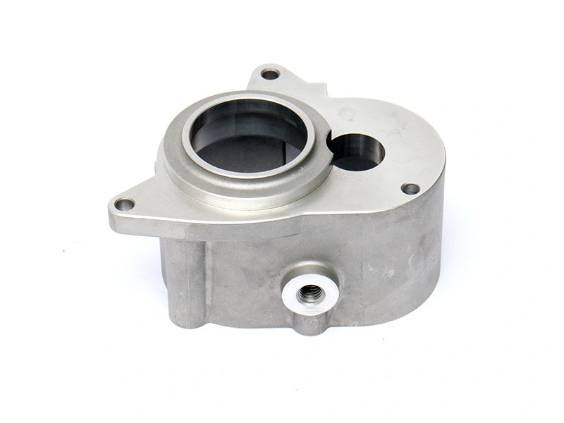
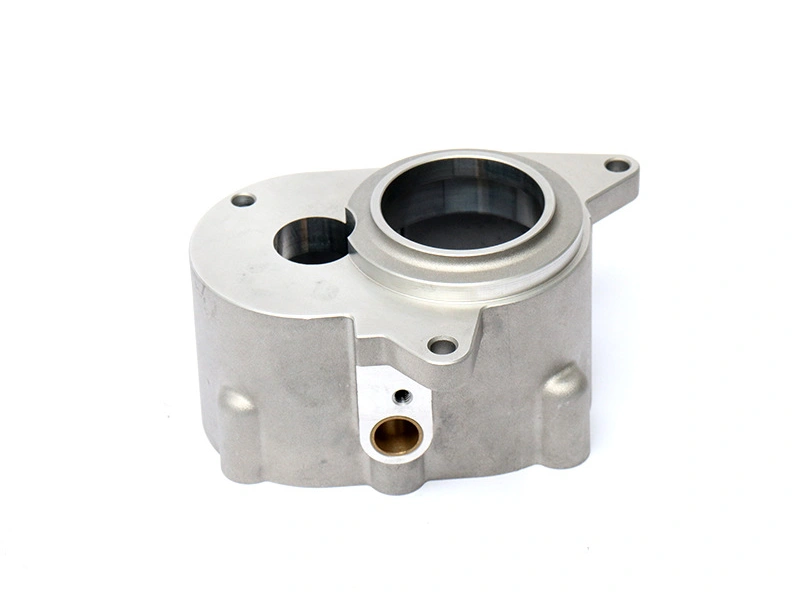
Parting lines affect die-cast part quality because they are the interfaces where the tool halves meet and the casting separates from the die. Their location and condition influence flash, mismatch, witness marks, trimming, draft, surface appearance, and the ability to machine or inspect nearby features. A parting line is not automatically a defect. It becomes a quality problem when it crosses a sealing face, locating surface, visible edge, thin wall, or other feature whose function cannot tolerate the resulting variation.
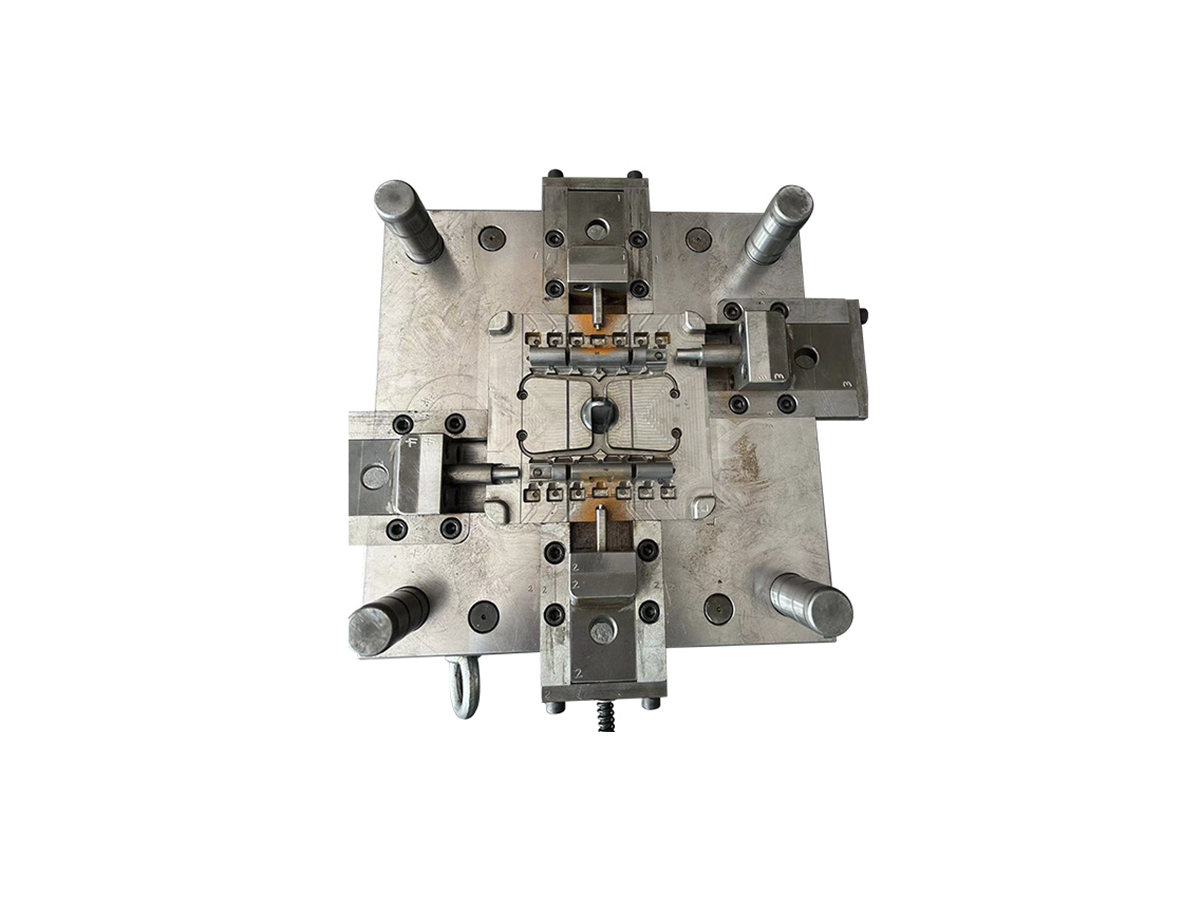
The correct location is a design and process decision. It should allow the tool to open, the casting to release, the metal to fill the cavity, and the finished feature to be trimmed or machined without creating avoidable risk. The alloy, die direction, slides, cores, gates, vents, ejection, and downstream fixture all matter. A visually clean line on a computer model does not prove that the production interface will remain stable through thermal cycling and tool maintenance.
Quality Effects to Review
Flash can form when metal enters a small gap at the parting surface. A trim operation may remove it, but trimming can leave a witness, shift an edge, or damage an adjacent thin wall. Mismatch occurs when the two tool halves or an insert do not align as intended. It can change a diameter, create a step, interfere with assembly, or force additional machining. A parting witness may be acceptable on a hidden nonfunctional area and unacceptable on a gasket land or appearance face.
Draft and ejection also connect to the parting line. If a wall has insufficient release direction, the casting can drag, stick, or distort as the die opens. If ejectors push near the line or a thin flange, they may create local marks or deformation. A slide or core introduces another shutoff interface that can behave like a secondary parting line. Those interfaces should be mapped to the finished drawing before the tool is released.
Keep Functional Surfaces Away or Machined
A common choice is to place the parting line on a nonfunctional edge and leave it within a controlled trimming zone. That works when the edge has enough clearance and the remaining witness is acceptable. If the line must cross a locating bore, sealing flange, bearing seat, or mounting pad, plan a machining operation and adequate stock. The machining setup must reference stable datums rather than flash or a mismatch that changes from part to part.
Surface treatment adds another boundary. Paint, powder coating, plating, or conversion treatment can make a witness more visible, build on a sharp edge, or expose a line during preparation. Identify visible surfaces and mask or finish them according to the delivered condition. Neway's post-machining route should be reviewed with the proposed parting line when a finished interface depends on removing the casting witness.
Parting-line situation | Main risk | Useful control |
|---|---|---|
Hidden trim edge | Flash or witness affects clearance or assembly | Define trim boundary, edge clearance, and visual limit |
Sealing or locating face | Flatness, leak path, or position changes after release | Move the line or machine the face from functional datums |
Visible exterior surface | Witness, mismatch, or finish buildup is noticeable | Relocate, blend, mask, and approve a representative finish sample |
Slide or insert shutoff | Local flash or movement changes a feature | Inspect shutoff, alignment, wear, and maintenance condition |
How to Verify the Line
Use visual inspection to assess flash, witness, sharp edges, and surface appearance. Use dimensional measurement when the line is near a controlled edge, diameter, flange, or datum. Inspect the part in the state named by the drawing: as-cast, trimmed, machined, coated, or assembled. A raw casting check cannot close a requirement that applies after machining or finishing.
During a tool trial, record the line location, trim result, mismatch, ejector marks, and any change made to the tool. If the tool is repaired or an insert is replaced, recheck the affected feature. The tool and die making plan is complete only when the parting decision connects to the finished part and its inspection method.
Parting-Line Review Before Tool Release
Before releasing the tool, overlay the proposed parting line with the part drawing and mark every crossing of a datum, seal, bore, thread, visible edge, and thin section. For each crossing, state whether the surface remains as-cast, is trimmed, or is machined. Also record the expected witness direction and how a gauge or fixture will reach it. This review prevents a later quality dispute in which the supplier considers a line normal and the buyer considers the same line a functional defect.
Parting lines affect quality through the features they cross and the operations that follow them. Buyers should approve their location with the part function, not reject or accept a line based only on appearance.
Parting Line and Trim Strategy
The trim plan should be designed with the line, not added after the tool is complete. Show where flash will be removed, where a trimming blade or fixture can reach, and which edge must remain controlled after trimming. A line close to a boss, rib, or thin flange may leave too little support for the trim operation even when the cavity itself is correct.
For a cosmetic housing, approve a representative trimmed and finished surface because blasting, painting, or plating can reveal a witness that is unobtrusive on the raw casting. For a machined feature, define the datum and stock that remove the line without moving the functional edge. The practical question is not whether a parting line exists; it is whether the planned next operation can control its effect.