What Are the Main Parts of a Die Casting Tool?
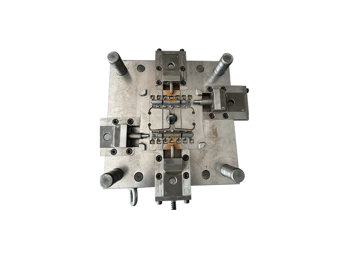
The main parts of a die-casting tool are the cavity, core, parting surfaces, gates and runners, vents or overflows, cooling passages, ejectors, and any slides, lifters, inserts, or interchangeable wear components needed by the part. Together they control how molten alloy enters, fills, cools, and leaves the tool. A buyer should judge the tool as a working system because a well-machined cavity cannot compensate for poor venting, unstable ejection, or an unplanned parting line.
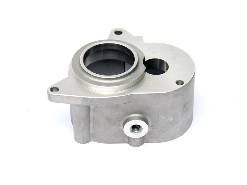
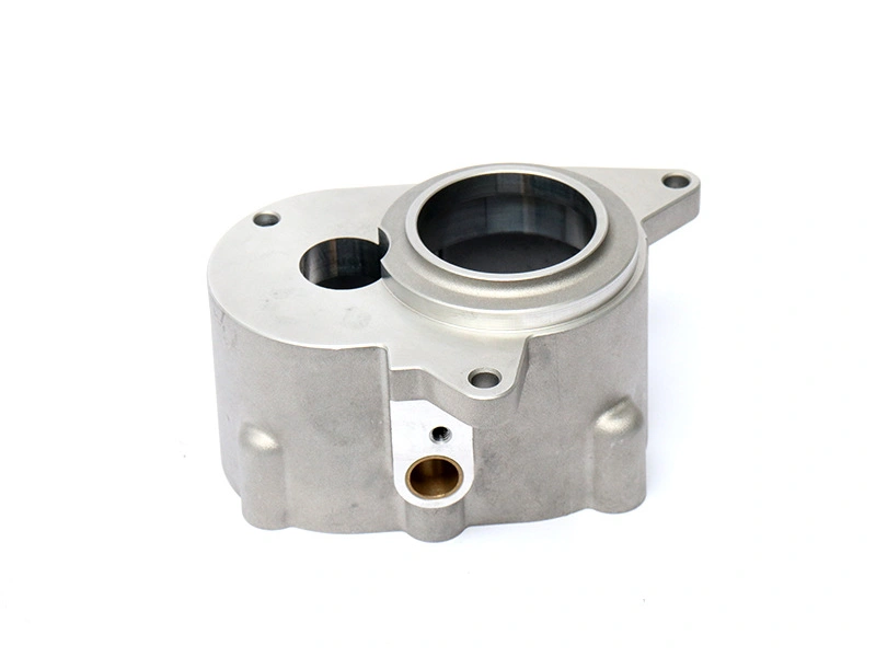
The exact arrangement depends on the alloy, casting process, geometry, volume, surface requirement, and downstream machining. An aluminum housing with a deep internal pocket may need a different core and cooling arrangement from a zinc hardware part. A threaded boss, side opening, or undercut can introduce a slide or insert. The tool drawing should show those relationships clearly enough for design, purchasing, and inspection teams to understand what the quotation includes.
Shape-Making Components
The cavity forms the outside surfaces of the casting, while the core forms internal geometry such as bores, pockets, or passages. The parting surfaces determine where the tool opens and where the casting separates from the two halves. These surfaces also influence flash, mismatch, draft, witness marks, and the amount of trimming or machining required. A parting line placed on a functional sealing face may create unnecessary cleanup or inspection risk even when the outer silhouette looks attractive.
Slides, lifters, loose inserts, and other moving elements create geometry that cannot be released along the primary die direction. They are useful for side holes, undercuts, or internal features, but each one adds alignment, wear, venting, cooling, and maintenance questions. A replaceable insert can protect a wear-prone detail or make a future repair practical. It can also create a joint line that must be kept away from an important surface or controlled during trimming.
Metal Delivery and Air Control
Gates and runners deliver molten alloy to the cavity. Their location and size influence filling direction, thermal balance, trimming, and the zones that may need special inspection. Vents and overflows help manage displaced air and late-flow metal. They do not make every casting leak-tight or eliminate all internal discontinuities; their effectiveness depends on the tool, alloy, thermal condition, and process settings.
For a pressure-sensitive housing or machined passage, ask where the gates, overflows, and vents are located relative to the finished feature. A gate witness may be harmless on a hidden trim edge but unacceptable on a visible face. An overflow may support filling but require a trim operation that changes fixture access. These are part-design and process decisions, not merely tool-detail drawings.
Parts Must Be Read as a System
The same component can influence more than one quality question. A slide may form a side opening, but its shutoff can also affect flash and its cooling access can affect cycle stability. An ejector may release a part, yet its witness can fall on a visible surface or distort a thin flange. When reviewing the tool, follow each feature from metal entry through cooling, release, trimming, machining, and inspection. This makes the component list useful for comparing quotations and planning maintenance.
Thermal and Release Components
Cooling passages remove heat from selected tool regions and help manage thermal differences between thick and thin sections. The circuit must be accessible, sealed, and kept clear of cavity surfaces, inserts, slides, and fasteners. Uneven cooling can contribute to distortion or inconsistent surface condition, but the final result also depends on metal temperature, cycle conditions, ejection, and the stiffness of the casting.
Ejector pins, sleeves, blades, or other release features push the part from the die after solidification. Their locations must provide enough support without leaving unacceptable marks or pushing on weak walls. Ejector layout also affects deformation, sticking, and how the part can be handled before trimming. The tool-material selection should be evaluated alongside these loads and wear locations, not as an isolated steel choice.
Tool group | Primary job | Part evidence to review |
|---|---|---|
Cavity, core, and parting | Form the required external and internal geometry | Draft, mismatch, flash, functional datums, and machined stock |
Gates, runners, vents, overflows | Deliver metal and manage air and late-flow material | Fill observations, trim condition, surface zones, and internal-risk review |
Cooling and ejection | Control heat and release the solidified casting | Distortion, ejector witnesses, sticking, and free-state dimensions |
Slides and inserts | Form side features or isolate wear and repair areas | Alignment, shutoff, flash, access, replacement, and maintenance records |
What the RFQ Should Name
Request the tool layout, parting proposal, moving-element list, gate and overflow plan, venting approach, cooling concept, ejector locations, insert strategy, tool material, tryout scope, spare or replacement items, and maintenance boundary. Link each item to a part feature or risk. Neway's die-making service can then be compared on the tool system and its evidence, not on a generic promise that a cavity will be machined.
In short, the main die-casting tool parts have different jobs, and their interaction determines casting quality. The best review follows the alloy from entry, through filling and cooling, to ejection, trimming, machining, and inspection.