What Does Die Mold Machining Include?
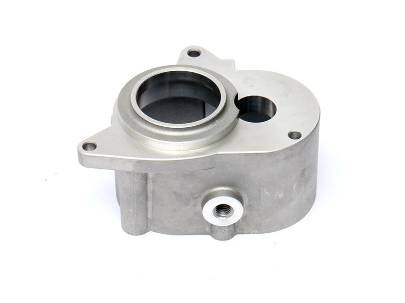
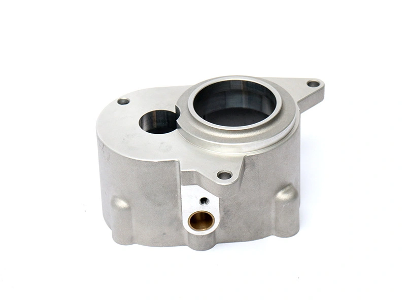
Die mold machining includes the controlled manufacture and inspection of cavity, core, parting, insert, shutoff, cooling, venting, ejector, and other tool features that form and release a casting. It is not the same as machining a finished part. The toolmaker is creating surfaces that will later transfer geometry to many castings, so datum control, surface condition, alignment, thermal access, and tryout evidence all belong in the scope.
The actual scope depends on the alloy, casting route, part geometry, volume, surface requirement, downstream machining, and maintenance plan. A simple open shape may need fewer moving elements than a housing with side ports, deep pockets, thin walls, or replaceable inserts. Buyers should ask how the machined tool will prove the functional features of the finished casting rather than compare only machine hours or a steel grade.
Shape-Making Machining
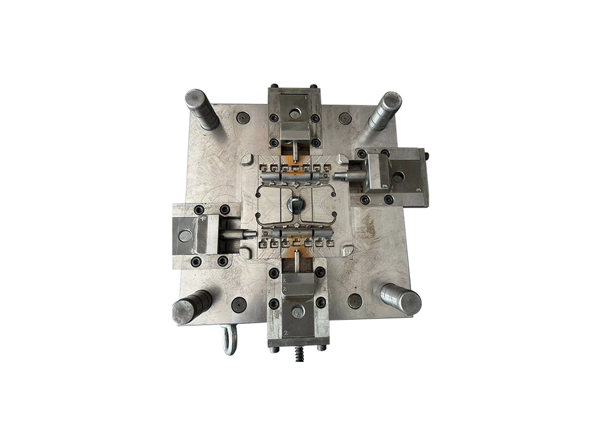
Cavity and core machining creates the external and internal surfaces of the casting. Parting-surface machining controls how the tool halves meet and how flash or mismatch can develop. Shutoffs close around slides, inserts, or core features. The tool drawing should identify draft, die direction, parting locations, critical radii, and surfaces that will later be machined on the casting.
Moving elements add machining and fitting work. Slides, lifters, and inserts need alignment, clearance, wear control, and a repeatable home position. A small mismatch at a shutoff can become a repeated flash line. An insert may make a repair practical while introducing a joint witness. Inspect the tool in the assembled state, not only as separate blocks on a machine.
Thermal and Release Machining
Cooling passages, vents, ejector bores, and access features must be located relative to the cavity and core. Cooling cannot interfere with fasteners, inserts, slides, or cavity surfaces. Vents and overflows need access for cleaning and maintenance. Ejector features should support release without pushing on a thin wall or a cosmetic face. These details connect the tool machining plan to the casting condition and later inspection.
Machining accuracy in the cooling circuit does not automatically prove thermal uniformity in production. Flow, metal temperature, cycle conditions, mold contact, and maintenance also matter. The buyer should record the design assumption and the trial observation that will verify it.
Machining scope | Tool function | Evidence to review |
|---|---|---|
Cavity and core | Transfer outside and inside part geometry | Datum inspection, surface condition, draft, and casting dimensions |
Parting and shutoffs | Close the tool and control flash and mismatch | Assembled fit, witness, flash, alignment, and repeat check |
Slides and inserts | Form undercuts or isolate wear and repair areas | Movement, home position, clearance, wear, and replacement access |
Cooling, vents, ejectors | Manage heat, air, and casting release | Passage access, ejection marks, release, distortion, and trial records |
Inspection and Tryout Are Part of Machining
Tool inspection should use the agreed datum system and identify the surfaces that control the finished casting. Check cavity and core dimensions, parting alignment, inserts, slides, cooling connections, vents, ejectors, and surface condition. Then run a production-representative tryout and inspect the casting before and after planned machining. A tool can pass a machine report and still produce a part with fill, release, or fixture problems.
Neway's tool and die making service should be reviewed with the part drawing and downstream post-machining plan. State the correction record and the features that must be rechecked after a cavity, insert, parting surface, or ejector is changed.
Commercial Boundary
A useful die mold machining scope names the tool materials, cavity and core work, moving elements, cooling and venting, inspection, tryout, corrections, spare parts, maintenance access, and release records. It also states what is excluded, such as production casting, trimming, CNC machining, finishing, or validation tests. That clarity lets purchasing compare like-for-like quotations.
Die mold machining is complete only when the tool geometry and the trial evidence support the specified casting route. Machine accuracy is necessary, but the buyer also needs proof that the tool functions as a casting system.
Machining Scope by Tool Stage
At the design-to-steel stage, the scope includes datums, parting, draft, cavity and core surfaces, inserts, slides, gates, vents, cooling, and ejection. At the assembly stage, it includes fitting, shutoff closure, movement, plugs, connections, and access. At the trial stage, it includes the measurements and casting observations needed to decide whether a correction is required.
Separate tool evidence from part evidence. A coordinate report can show where a cavity was cut; a trial casting shows whether the cavity fills, releases, trims, and supports the intended machining. The finished sample then shows whether the fixture, stock, surface, and functional interfaces work together. Buyers should state which of these stages are included in the quoted tool package.
Also name the exclusions that could otherwise be misunderstood: production casting, trimming, CNC work, coating, leak testing, destructive sectioning, spare inserts, and long-term storage. A precise scope protects both the toolmaker and the buyer because later requests can be linked to a defined feature and acceptance record.