Minimum Wall Thickness for Aluminum Sand Casting: Draft, Cores and Machining Allowance
There is no single minimum wall thickness that applies to every aluminum sand casting. A practical wall is determined by the alloy, mold material, pattern quality, section size, flow distance, core arrangement, pouring conditions, draft, local ribs and bosses, machining allowance, and the acceptance requirement. A short, well-fed wall may cast successfully at a different thickness from a long wall that must fill around a corner or beside a heavy section. Buyers should use a minimum-wall question to start a DFM review, not to demand an unsupported universal number.
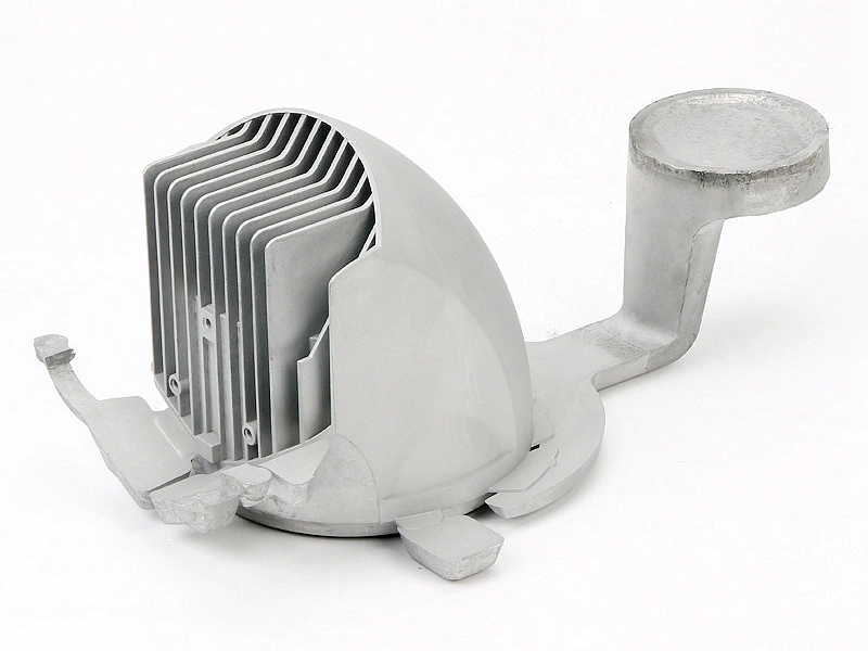
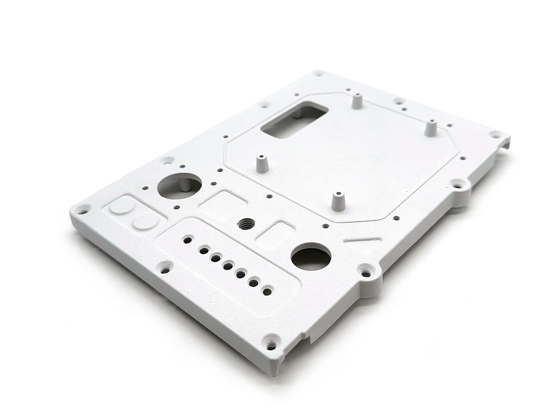
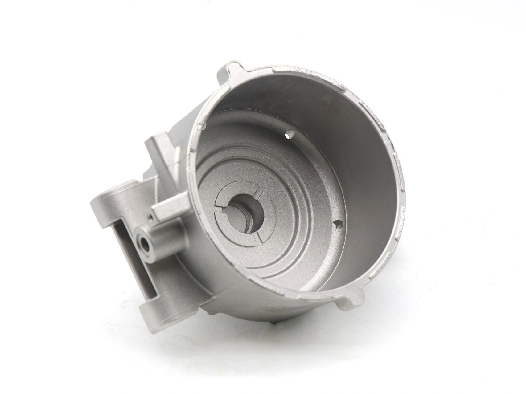
For custom sand castings, sand casting is often considered for prototypes, large parts, complex internal passages, or low-to-medium production conditions where a permanent die is not the first choice. The process offers design freedom, but the as-cast surface, dimensional variation, draft, cores, and machining stock must be included in the finished-part plan. A nominal wall that looks acceptable in CAD can still create a heavy section, a difficult core, or a thin area after machining.
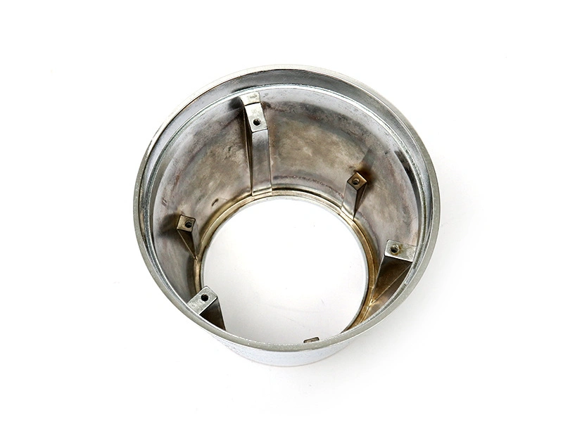
Minimum Wall Is a Location-Specific Requirement
A minimum wall should identify a location and a function. A broad external panel, a narrow web, a curved shell, a wall around a core, and a sealing land can each need a different design response. The drawing should show nominal wall, local minimum, adjacent heavy sections, ribs, bosses, openings, and machined faces. If the wall is structural or pressure-sensitive, mark that zone separately from a cosmetic or nonfunctional wall.
Long flow paths reduce the usefulness of a simple wall number. Metal can lose heat as it travels through the mold, and a thin end region may not fill or feed like a short section near the gate. A corner or internal feature can create a local flow shadow. The supplier should identify how the proposed pour, gate, runner, or gating direction reaches the thin zone. A wall may be acceptable after changing the fill direction even when adding metal would make the design heavier.
Wall thickness also interacts with mold handling. A thin sand wall between cavities or around a core can be vulnerable to erosion, breakage, or movement during closing. The pattern may require reinforcement or a changed parting arrangement. A core print that is too small can affect alignment; a core that is too large can add weight and cost. These are tooling and molding decisions, not just CAD dimensions.
Wall location | Main sand-casting concern | Review question |
|---|---|---|
Broad exterior panel | Flow distance, flatness, distortion, and visible surface | Where is the feed path and what surface condition is acceptable? |
Wall around a core | Core support, alignment, gas release, and local feeding | Can the core be located and inspected without making a heavy section? |
Wall beside a boss | Section change, shrinkage, and machining exposure | Can the boss be hollowed or blended into the wall? |
Machined face | Stock, as-cast variation, and subsurface discontinuities | What datum and final allowance are required? |
Alloy, Pour, and Solidification
Aluminum casting alloys differ in fluidity, solidification range, shrinkage behavior, machinability, corrosion response, and heat-treatment options. The alloy choice should follow the part function and the selected sand-casting route. A material that is attractive for strength may require a different feeding strategy from one selected for fluidity or machining. Do not approve a minimum wall until the material designation and condition are defined.
Pouring temperature and mold condition affect how a thin section fills, but they should not be treated as a license to push the process beyond a stable window. Excessive temperature can increase reaction, gas, oxidation, or mold damage risks. Insufficient temperature can reduce fill length. The supplier should determine the process range against the alloy, mold, section size, and equipment. A buyer needs the risk and the evidence, not an unexplained temperature promise.
Solidification is influenced by section changes. A large boss beside a thin wall can remain hot while the wall has already started to freeze, and that imbalance can contribute to shrinkage or distortion. Use gradual transitions, hollow bosses where appropriate, ribs that are not simply thick blocks, and feeding features that can be removed without damaging the functional surface. The final choice should be verified on a representative sample.
Draft, Parting, and Pattern Practice
Sand-casting patterns need draft so they can be removed from the compacted sand without tearing the mold. The required draft depends on pattern material, molding method, surface, depth, and whether the face is later machined. A tight draft can preserve envelope dimensions but increase mold damage or operator sensitivity. A larger draft can simplify production but may alter a mating surface. Show the draft direction and identify faces where it is functionally constrained.
The parting line should avoid sealing faces, close-tolerance bores, and high-visibility areas where possible. If it crosses a functional surface, the supplier should explain the mismatch and finishing route. Cores should have stable prints, access for placement, and a gas-release plan. A deep narrow core may be more difficult to support than a broader one. A hollow feature that seems cheap in CAD can require multiple cores or a complicated mold closure.
Pattern wear and mold variation can change the effective wall. That is why the finished drawing should distinguish as-cast and machined surfaces. Do not allocate machining stock on every face by default. Extra stock adds metal, machining time, and the possibility of opening discontinuities. Allowance should be based on the casting variation and the final functional dimension.
Ribs, Bosses, and Wall Transitions
Ribs can stiffen a casting without increasing the full wall thickness, but they still affect molding and solidification. A rib that is too thick can create a hot section and a visible sink or shrinkage concern. A rib that is too thin may be difficult to mold, clean, or inspect. Blend the rib into the wall and review its draft, height, spacing, and orientation. If a rib is used as an assembly stop or datum, state that function clearly.
Bosses for fasteners, bearings, inserts, or pipe connections need local support and a controlled transition. A solid boss may be easy to model and difficult to feed. A cored or hollow boss may reduce section change but add a core or machining step. The right choice depends on the load, insert method, final hole, and production volume. Buyers should compare the total route rather than the number of casting operations alone.
Inside corners, outside corners, and flange intersections should use radii appropriate to the mold and the part function. A sharp inside corner can become a stress concentration and a mold-damage location. A radius that is too large can interfere with a gasket, insert, or mating face. Define the important radius and let the supplier propose a manufacturable transition for approval.
Design feature | Potential wall-thickness effect | Evidence to review |
|---|---|---|
Rib | Local hot section or difficult mold draw | Section review, draft check, and as-cast surface inspection |
Solid boss | Delayed cooling and shrinkage near the wall | Feeding review, section inspection, and final hole or insert trial |
Cored boss | Better section control but more core alignment work | Core-print review, location check, and machining plan |
Flange junction | Heavy intersection or distortion during cooling | Transition geometry, flatness, and finish machining check |
Cores and Internal Features
Cores create passages, cavities, undercuts, and internal shapes that the pattern alone cannot form. They also introduce core prints, venting, coating, movement, breakage, and removal considerations. A core that is not adequately supported can shift and change wall thickness from one side to the other. A core that traps gas or moisture can contribute to internal defects. The casting drawing should identify which internal dimensions are functional and how they will be inspected.
Thin walls around a core need enough process margin for core placement and mold closing. If the gap is too small in one region, the core may be difficult to align or the sand may break. If the gap is too large, the part may be heavy or the cavity may require more machining. Ask the supplier to show a section through the core prints, the minimum metal around the feature, and the removal or cleaning method.
For a pressure boundary, the interior surface is not automatically acceptable just because it is hidden. A connected pore, core shift, or rough region can affect leakage, flow, or assembly. Specify the test method and the boundary. A visual check of the exterior cannot prove an internal passage.
Machining Allowance and Finished Wall
A buyer should distinguish a minimum as-cast wall from the minimum wall remaining after machining. If a pocket is machined deeply into a casting, the finished wall can be much thinner than the nominal CAD envelope. The machining toolpath, fixture datum, and expected as-cast variation all influence the result. Post-machining should be included in the design review when a casting is intended to become a precision or sealed component.
Use functional datums for the fixture rather than assuming a rough sand surface is a stable reference. A face may need enough stock for a first cleanup cut and a final pass, but more stock is not automatically safer. Heavy removal can expose shrinkage, alter balance, and increase cycle time. The supplier should explain how the allowance was selected and which dimensions are controlled as-cast.
After machining, inspect wall thickness at the critical sections and relate it to the drawing datums. A point measurement is not enough if the wall varies along a long path or around a core. For thin or pressure-sensitive parts, consider sectioning a qualification sample, non-destructive inspection, leak testing, or a functional assembly test as appropriate to the risk.
Defect and Inspection Planning
Thin sand-cast walls can be affected by incomplete fill, cold shuts, inclusions, gas defects, shrinkage, core shift, mold erosion, and dimensional variation. The correct containment depends on the defect and location. A surface mark on a hidden face may be acceptable; a discontinuity in a machined sealing land may not be. Define sensitive zones and inspect the finished feature that carries the function.
Visual inspection can identify surface condition and gross mold damage. Dimensional measurement checks wall-related geometry and core location. Sectioning can reveal internal condition in a defined sample. Leak testing can address a pressure boundary. Radiographic or other non-destructive methods may be considered where the requirement and equipment support them. Do not list a test without defining the location, sample, condition, and pass/fail rule.
Qualification samples and routine production inspection should not be confused. A detailed section review may be appropriate during process development, while production may use dimensional, visual, and functional checks at an agreed frequency. The plan should preserve the alloy, pattern or tool revision, mold condition, and inspection records so that a repeat order can be compared with the approved route.
RFQ Inputs for Aluminum Sand Casting
Send the 3D model, controlled drawing, alloy, part envelope, nominal and minimum wall map, cores, draft direction, machining faces, annual and lot quantity, surface requirements, pressure or load function, inspection method, and packaging. Mark critical walls and tell the supplier whether 3 mm or another value is a nominal target, a local minimum, or a finished dimension after machining.
Ask for a response showing the pattern or mold approach, parting line, cores, gating and feeding concept, draft changes, heavy sections, thin zones, machining allowance, fixture datums, and proposed validation. Request that unsupported minimum-wall guarantees be replaced by a condition-based statement tied to alloy, geometry, molding method, and inspection.
Neway's sand-casting service can be considered when the part's volume, size, internal geometry, and validation stage fit the route. The final scope should separate pattern or tooling, casting, machining, finishing, inspection, and any special test. That makes the wall-thickness decision visible in the quotation.
Why a Wall Map Is More Useful Than One Minimum
Review the casting as a map of locations rather than as one nominal thickness. Mark long unsupported spans, corners where metal changes direction, areas beside a riser or heavy boss, and surfaces that will be cut away in machining. A wall that is short and directly fed may be less demanding than a nominally thicker wall at the end of a long flow path. The map also shows where a core may need support. If the core is slender or poorly anchored, the problem is not only filling; the finished wall can move because the core shifts during mold closing or pouring.
Transitions should be judged with the neighboring volume. A heavy boss joined directly to a thin wall can create a hot spot and local shrinkage even when the thin wall itself fills. A rib can improve stiffness, but a sharp rib-to-wall intersection can become a stress concentration or a difficult sand feature. Rounded transitions, sensible rib proportions, and a clear feeding path reduce the need to rescue the design with extra metal. The final geometry should be checked after adding draft and machining stock, not only in the nominal CAD model.
Core Stability and Finished Wall Control
Internal cores change the way wall thickness is controlled because the outside mold and the inside core each have their own location, movement, and dimensional variation. Core prints need enough engagement for stable location, but they should not create an unnecessary thick section that is difficult to feed. Long cores may need support or a design that allows the foundry to handle them without damage. The RFQ should identify which internal dimensions are functional and which are simply clearance, because both do not deserve the same machining and inspection effort.
Machining allowance is another part of the minimum-wall question. If a face is to be milled or bored, the casting must contain enough stock to clean the surface while leaving the final wall and adjacent feature intact. Too little stock exposes sand variation or an incomplete surface; too much stock increases mass, cutting time, and the risk of opening a subsurface void. The supplier should show the as-cast section, the allowance, and the finished section for sensitive areas.
Validate Thin Sections Without Overpromising
For a thin or remote wall, validation should focus on repeatable evidence. A representative mold and core arrangement can show whether the section fills, whether the surface contains connected defects, and whether the wall remains stable after shakeout and cleaning. If the section is part of a pressure boundary, visual inspection alone is not enough. The agreed leak or pressure method, test medium, test condition, and reject criteria should be defined by the application owner. If the section is structural, inspection should connect the wall location to the load path and to any machining or joining operation that follows.
It is also useful to separate a design feasibility sample from a production acceptance sample. Early samples may prove that the geometry can be molded and poured, while later samples prove the approved process and inspection method. Treating those samples as the same evidence can hide a change in pattern, core practice, alloy, or finishing operation. The quote should state what is included in each stage and which decisions remain open.
Neway's sand-casting route can be assessed with the wall map, core plan, and finished machining drawing in one review. The buyer should ask for condition-based recommendations, not a bare minimum number detached from the part.
If the final wall contains a machined interface, compare the sand-casting route with the broader metal casting scope while keeping the same datum and acceptance requirement.
Buyer Summary
The minimum wall thickness for aluminum sand casting is a location-specific engineering decision. It must be checked against flow distance, alloy, mold, cores, draft, transitions, machining allowance, and the function of the finished part. The safest design review asks how the wall will be formed, supported, machined, and inspected rather than asking for one universal number.
Use a wall map, identify the sensitive sections, and require evidence from a representative casting. This approach gives design and purchasing teams a defensible basis for choosing aluminum sand casting without confusing a nominal CAD wall with a guaranteed production capability.
FAQ