
What Is a Watch Case Middle Frame? Zamak Die Casting
A watch case middle frame is the body between the bezel and the case back, and on a 38.0×38.0×9.5 mm square case it carries every seat. The frame is Zamak 5 to ASTM B86 AC41A at a 12±1 g target, with 0.9–1.2 mm side walls and 18–27 µm of Cu/Ni/Cr. Zinc die casting sets the shape once, and four later cuts set the fits.
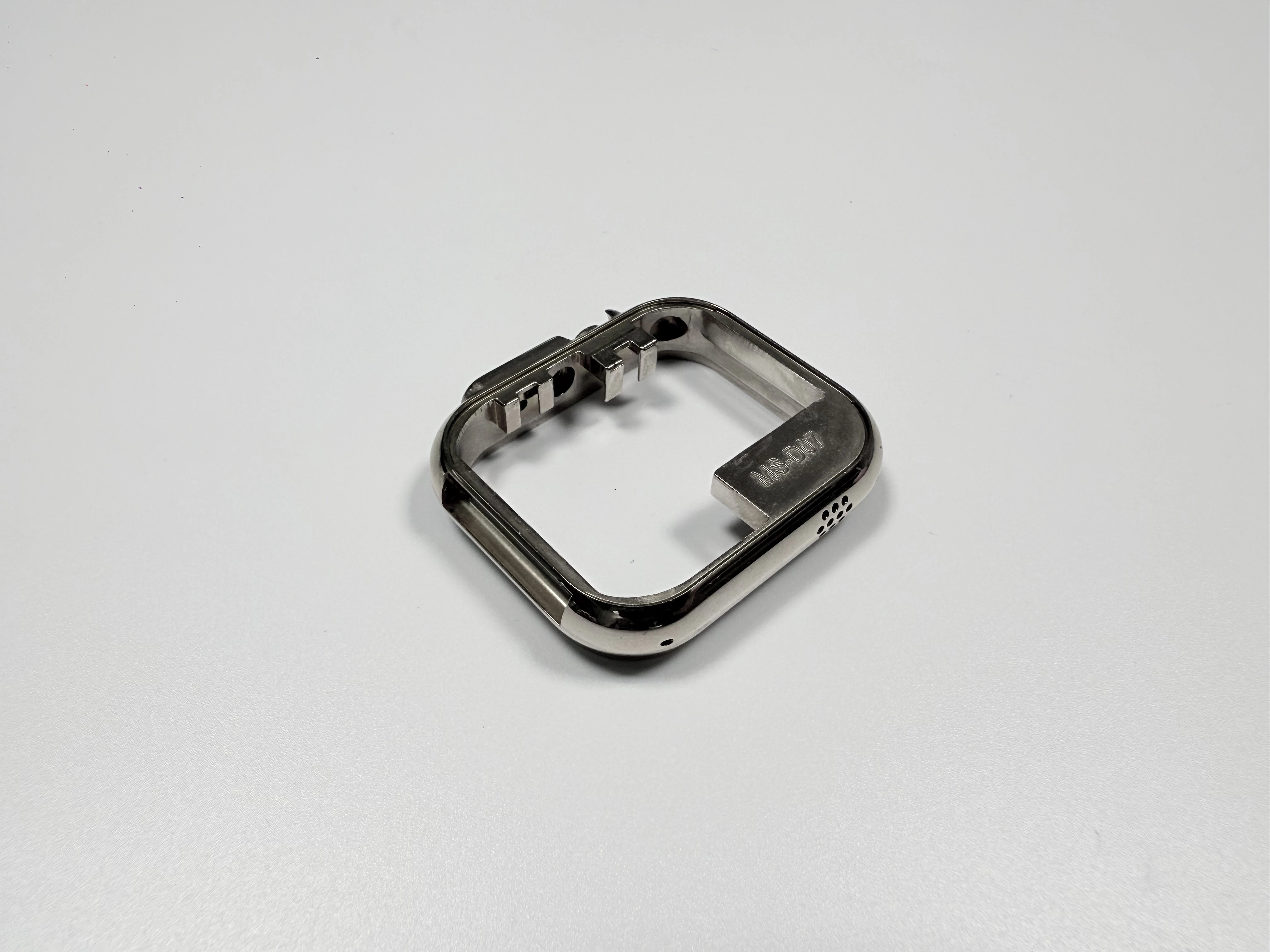
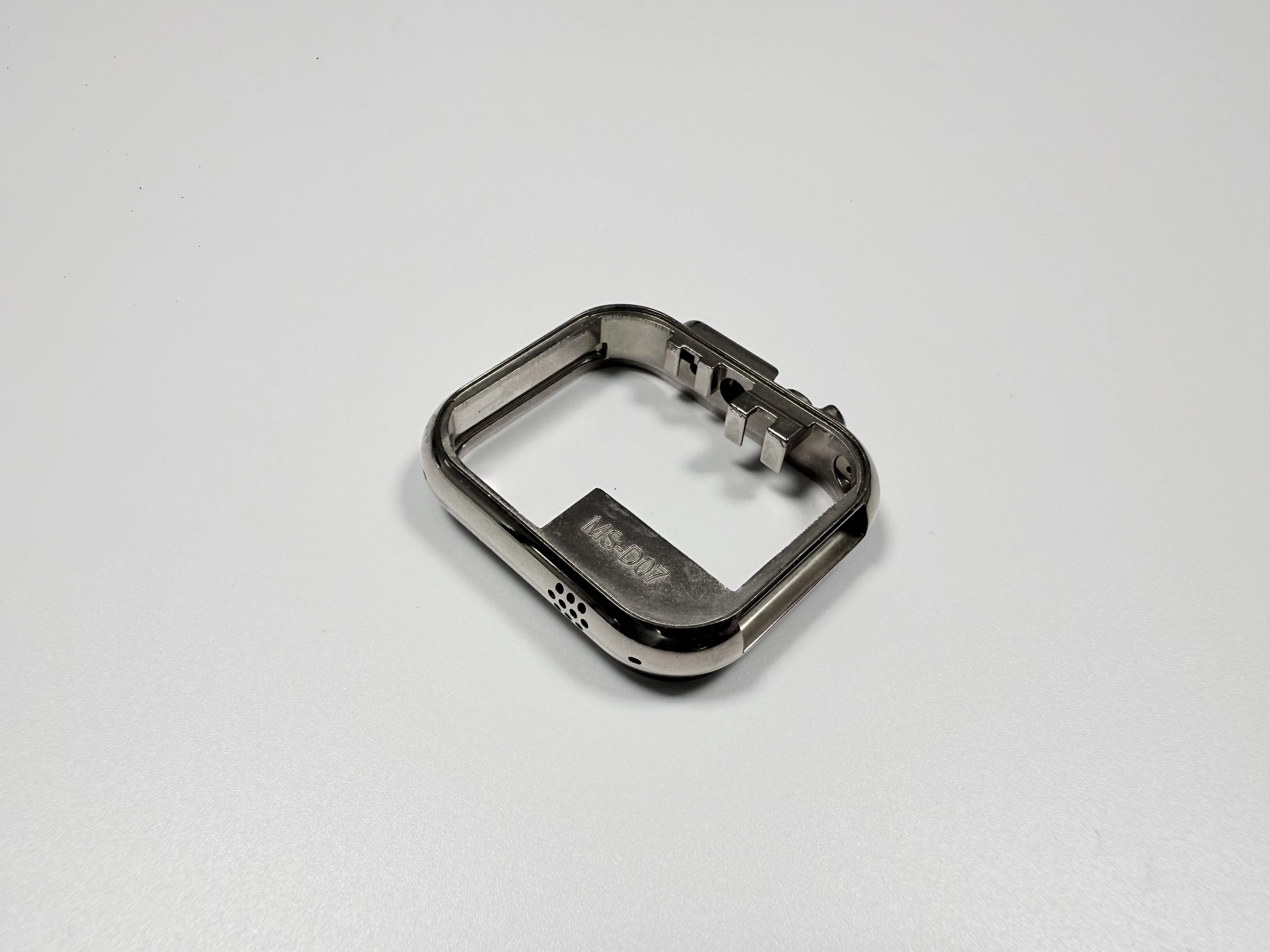
What does a watch case middle frame hold?
The frame is the load path between the crystal and the wrist. A bezel seats on its top face, a case back closes the bottom, and the movement ring drops into the inner cavity. Three duties follow: total height at 9.5±0.1 mm, gasket compression at the back, and two lug bores for the spring bars.
A seat that misses by its own thickness cannot be recovered at assembly, because the mating part has no second landing. The four seats are cut on one datum in one clamping.
Which four interfaces set a middle frame's tolerances?
Four interfaces decide whether the watch assembles: the bezel seat, the movement cavity, the crown hole, and the back face. The mirror step height is a 0.03 mm band on one side, 0–0.03 mm, and the inner cavity is 30.0 mm at a 0.05 mm upper deviation with a zero lower deviation. The crown hole is Ø3.0 mm on that same deviation, the lug bore Ø1.5 mm at a 0.03 mm upper deviation, and coaxiality between the lugs Ø0.05 mm.
Each interface is a separate cut, so a drawing that adds a fourth datum adds a line to the quote.
Why is the frame die cast in Zamak 5 rather than machined?
A machined stainless frame cuts four seats from solid, each in its own setup. Zamak 5 casts the shape in one shot, so machining covers four seats instead of the whole body, and 6.6 g/cm³ (typical) keeps the frame at 12±1 g.
The trade is tooling. Machining carries cost in cutting time per part, while a die is paid once and divided by the batch. The die cost is the largest part of the unit price at low volume, so a sample order can cost more on the casting route, and the crossover is a batch question.
Why does a 0.9 mm wall make the Ø1.5 hole hard?
The Ø1.5 mm bore is wider than the 0.9 mm wall it crosses. At each lug the drill exits into air, and the last turn leaves a thin ring that carries the thrust. The wall fails at the exit, not from thinness in service.
That geometry makes feed the controlling variable. A chip deeper than 0.1 mm at the mouth is a reject, because blending it takes the bore past its 0.03 mm upper deviation. The 0.9–1.2 mm range is a design target, and the low end sets the drill cycle.
Which matters more for a lug-hole breakout, feed or alloy?
Feed at breakthrough moves the breakout more than the alloy does. Zamak 5 folds at the exit rather than fracturing, so the remaining thrust rolls the burr longer, and a lower feed leaves a clean edge on the same wall.
An example record shows the size: 9 chipped lug bores in this batch of 300 pieces, none after a chamfer and a reduced feed. Because the cause sits in the drill cycle, the money goes into one more pass, not a new die.
How does 18–27 µm of plating amplify the 0.03 mm step?
The Cu/Ni/Cr stack is 18–27 µm per side, and the 0.03 mm mirror seat is 30 µm, so the coating is most of the feature it lands on. On a diameter the build reads twice, 0.036–0.054 mm, wider than the 0.03 mm upper deviation on a lug bore.
The seat cannot be finished after plating. A pass that removes the stack exposes zinc, and a pass that leaves it keeps the build, so the seat is cut before the plating line. Because it decides between a second cut and a rejected lot, the drawing says before or after coating. Layer choices sit in surface finishing for zinc castings.
How do gate and overflow positions change the lug-hole breakout?
Two die decisions move the breakout: where the gate lands and where the overflow runs. The gate sits at 12 and 6 o'clock on the thick lug walls, and the overflow at 3 o'clock on both sides of the crown notch. The gate must sit on the lug boss, and the price is the last metal landing beside the 0.9 mm wall that is about to be drilled.
The tool is four cavities in 8407 steel, built to a 300,000-shot design target. A four-cavity die multiplies the cost of a bad layout by four; the die cost is spread over the batch, not by cavity count. The layout also decides whether a pore ends in cut-away metal or in the cosmetic face. Because the gate sits in the die, a change after cutting is die work, not a process tweak.
Which gauge catches a 0.03 mm seat before plating?
The 0.03 mm seat is read on a granite plate with a feeler gauge, the lug bores with a plug gauge, coaxiality on a CMM, and coating thickness by X-ray.
Three tests load three layers: ASTM B571 at 200 °C for 1 h for adhesion, ASTM B117 at 240 h for the barrier, and ASTM B368 CASS at 48 h to grade 9 for the decorative face. A frame can pass salt spray and fail thermal shock.
The table below is a qualitative cross-check only, not an acceptance criterion; the criteria are the scrap lines and the three tests above.
Failure | What drives it | Where it is caught |
|---|---|---|
Chipped lug exit | Thrust at breakthrough | Plug gauge and bench check |
Rounded crown notch | Wheel on a thin edge | Contour comparison |
Blister | Pore under the stack | Thermal shock |
Tight bore after plating | Build on the diameter | Pin gauge |
CNC post-machining sets the seat and the bores before the plating line, and CNC machining holds the datum the gauge reads; the bore is read once pre-plate, once after plating to the drawing. A frame scrapped after plating has already paid for the plating, so the pre-plate gauge is cheaper than rework.
What makes a Zamak 5 watch case fail?
The mechanism fails on three duties: a diving rating, sustained abrasion, and a wall below 0.9 mm. It assumes a decorative case that meets sweat, friction, and daily knocks. Sweat and friction attack the 18–27 µm stack at the lug bore and crown tube, where the 0.1–0.3 µm chromium wears first.
A wall under 0.9 mm fails in the shot, after the die is paid. Stainless machined from solid leaves the 12±1 g budget behind, and painted zinc drops the 18–27 µm stack. Because the die is the fixed cost here, a duty past this line makes the die the wrong investment. A Zamak casting case records the same limit on another part: read the duty first, then the grade.
FAQ