Can a 0.9 mm Zamak Lug Wall Hold a 1.5 mm Pin Hole?
Yes: a Ø1.5 mm pin hole crosses a 0.9 mm Zamak 5 lug wall without a chipped mouth, when the exit is chamfered before the drill, the feed drops at breakthrough, and both lugs are cut in one clamping. The bore belongs to CNC machining rather than the die; a mouth chip over 0.1 mm is scrap.
Why does a 1.5 mm hole break out of a 0.9 mm wall?
The lug wall runs 0.9–1.2 mm as a target, so a Ø1.5 mm bore with a 0.03 mm upper deviation and no lower deviation is wider than the metal at its thinnest point. At the entrance the point cuts with zinc on both flanks; at the exit it meets a ring with air behind.
Breakout here is geometry, not grade. Zamak 5 to ASTM B86 AC41A holds 0.9 mm on both sides of the bore, so the alloy is not the weak part. The exit side carries no support, and once the point breaks through, the remaining ring is pushed out rather than cut.
What drives the breakout at the lug-hole exit?
Feed at breakthrough drives it. One example record lists nine chipped lug exits in 300 parts, all on the exit side.
A chamfer cut before the drill changes what the point meets: the edge already sits below the cutting plane. Lowering the feed as the point breaks through keeps the push small, and the next lot came back at zero.
Blending does not recover the part: the bore carries an upper deviation of 0.03 mm, so any blend takes it oversize and the plug gauge rejects it. A quote that lists drilling and no chamfer is short one pass.
How does one setup hold both lug holes to Ø0.05 coaxiality?
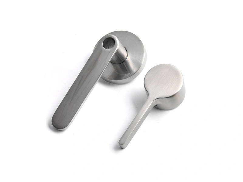
Both lug holes carry one spring bar, so Ø0.05 mm coaxiality belongs to a single axis, not two holes drilled well. Locating on the mirror step and indexing 180 degrees keeps fixture error in one clamping.
Flip the part for the second lug and the fixture offset enters the hole position before the drill reaches zinc. The two bores then sit on separate axes, and the spring bar binds.
A pin slid through both bores proves little: the bores are short and the pin bends. Video measurement or a CMM reads the two axes, and each clamping adds a line to the machining section of the quote.
Why is the lug pin hole drilled rather than cast?
A Ø1.5 mm core pin standing in a 0.9 mm wall bends under fill pressure, and this die runs four cavities, so four pins carry that load every shot. The gate can only sit on the thick lug wall at 12 and 6 o'clock, because the thick wall freezes last and the pressure must pass through it; the price is a peak on the weakest pin.
Drilling after the shot adds an operation and removes that failure mode. Tumbling runs before the drill, so the point starts on a face that has lost its gate stub; reverse the two and the drill walks on a burr.
Casting the hole means the die is paid once, and a chipped part loses the casting plus every machining step on it; drilling moves the money to the machining line, where a chip costs one chamfer.
What must a lug-hole drawing define before quoting?
Five items settle the feature: the bore at Ø1.5 mm, 0.03 mm over size at most and never under, Ø0.05 mm coaxiality, a chamfered exit to the drawing, no chip over 0.1 mm, the gauge, and a pre-plate or post-plate call.
Copper, nickel and chrome total 18–27 µm, which reads as 0.036–0.054 mm across a bore and is wider than the 0.03 mm deviation the drawing allows. A bore that passes Ø1.50–Ø1.53 pre-plate fails after plating, so gauge pre-plate to Ø1.536–1.554 and the re-cut stays off finished parts.
A quote built on zinc die casting alone covers neither that cut nor the chamfer.
Feature | Target | Allowed band | Gauge |
|---|---|---|---|
Lug wall | 0.9 mm | 0.9–1.2 mm | Section, video |
Pin bore | Ø1.5 mm | Post-plate Ø1.50–Ø1.53 mm (pre-plate 1.536–1.554) | Plug gauge |
Coaxiality | Ø0.05 mm | Ø0.05 mm max | CMM or video |
Mouth chip | 0 mm | 0.1 mm max | Video |
Copper | 10 µm | 8–12 µm | X-ray |
Nickel | 12.5 µm | 10–15 µm | X-ray |
Chromium | 0.2 µm | 0.1–0.3 µm | X-ray |
Send the lug section, gate position and plating callout with the RFQ; a supplier who answers all three can be compared with the next one.