Zinc Die Casting a Roly-Poly Coin Bank: Fit, Polish, PVD
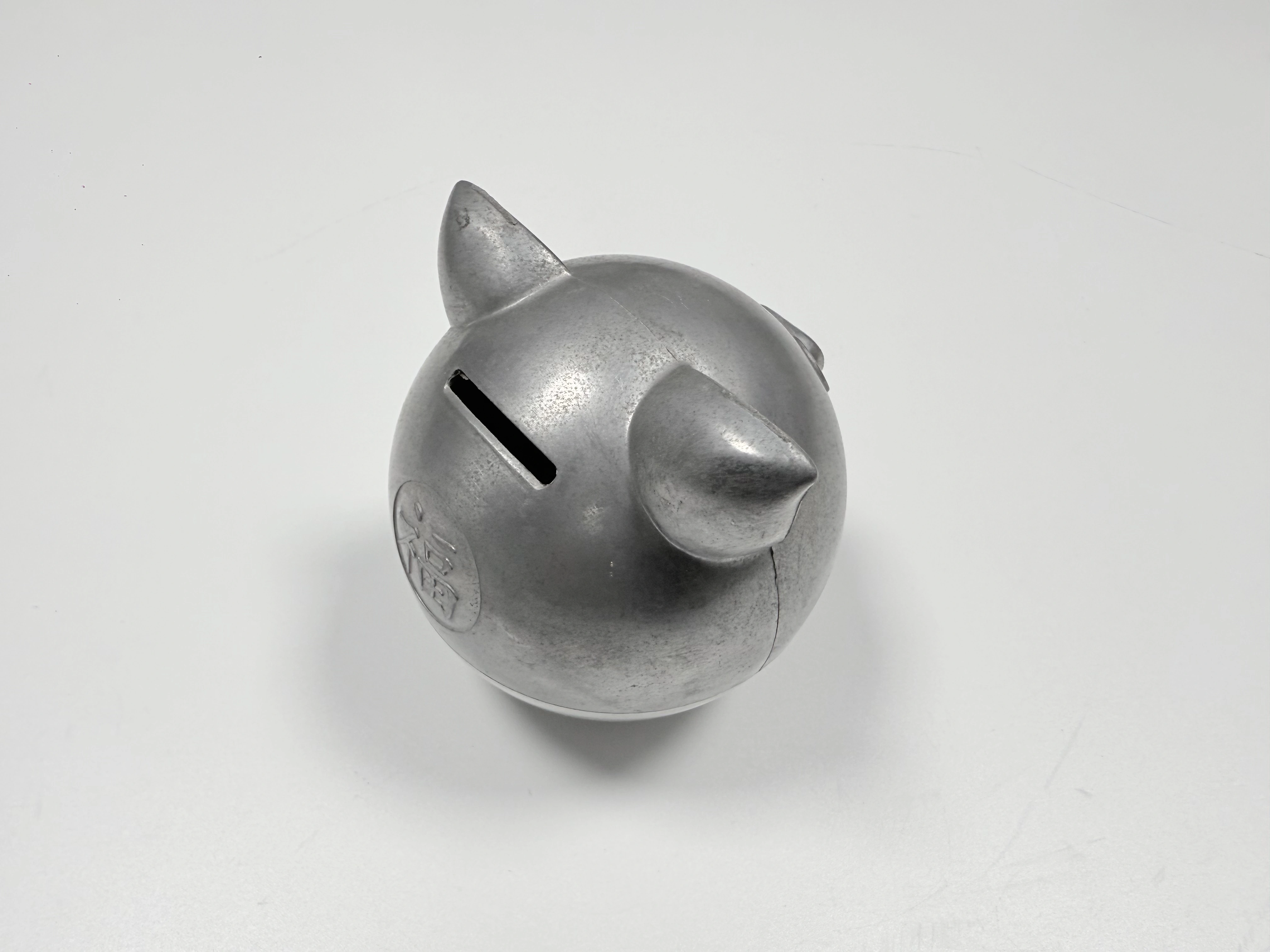
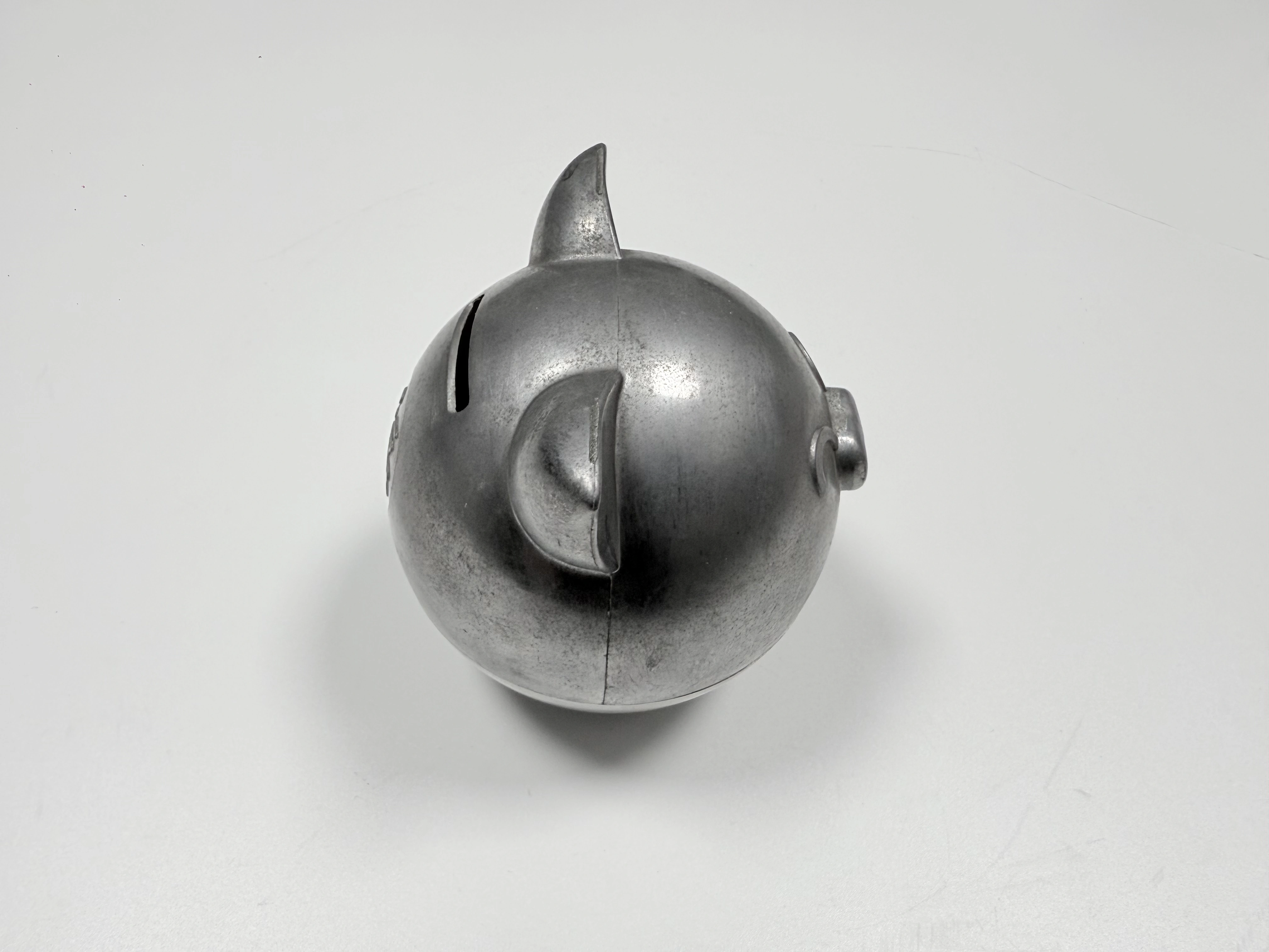
The seam decides whether a zinc die casting coin bank reads as a gift or as hardware. Two shells meet along the split line, and the drawing targets 0.05 mm there, read with a feeler gauge on the closed assembly. Polishing moves that seam, and a route that machines the mating face before the last polish pass cannot recover it afterwards. Change the order and the reading changes with it.
Three Dimension Sets: Why They Collide
Three dimension sets control this part, and three stages own them. The die sets overall height at 95 mm, the base at Ø60 mm, a wall of 1.2–1.5 mm, and a 12 mm base section. The finish cut sets flatness at 0.05 mm, and the coating adds 0.5–3 µm over whatever the polish left.
They collide because polishing sits between the second set and the third and removes metal from the edge that defines the joint. A tolerance the wheel can move is not controlled by the die or by the cutter. Control passes to whoever runs the last polishing pass.
General cast tolerances run to ISO 2768-1 class f; the mating face and the seam get their own callouts. Table 1 runs from the die to the assembly bench, and each line inherits from the one above.
Dimension | Target (mm) | Set at | Moved by |
|---|---|---|---|
Overall height | 95 | Die cavity | Draft and shrinkage |
Base diameter | Ø60 | Die cavity | Cavity block wear |
Wall section | 1.2–1.5 | Die cavity | Fill pressure, ejection |
Base section | 12 | Die cavity | Solidification order |
Mating face flatness | 0.05 | Finish cut | Clamp force, datum wear |
Assembly seam | 0.05 | Assembly | Polish stock, edge condition |
What the Bank Must Do: Three Jobs
The bank has to return upright after a push, hold a load of coins, and survive a retail shelf. Self-righting depends on the height of the center of gravity against the rocking radius, and the 12 mm integral base does that work at a finished 300 g. Coin load raises the center of gravity, so the balance check runs loaded.
Nothing in the shell profile creates that return. The hemisphere suggests the mechanism, and the mass distribution is the mechanism.
Alloy: Why Zamak 5
Zamak 5 (ASTM B86 AC41A) carries more copper than Zamak 3, which buys hardness and creep resistance at the same casting temperature. A 1.2–1.5 mm wall fills on a zinc shot without the thermal load of a hotter alloy, and the surface takes a polish to Ra 0.5 before a PVD film at 120–150 °C.
The trade is dimensional stability under sustained load. A part that must hold a bore for years belongs in a lower-copper grade, and a decorative shell with a cast weight in its base does not.
Base, Wall, Split Line: The Third Conflict
The base holds 12 mm of section, and the wall over it runs 1.2–1.5 mm. That step decides where the shrinkage lands. The thick section solidifies last; the thin wall freezes first and pinches the feed path.
What stays behind is porosity inside the base and a sink mark outside. Coating does not hide the sink; the film follows the depression and adds contrast, so the mark reads as a bright ring under a shelf light.
Fixes are geometric. Taper the base, run the gate into the thick section, cool the base separately, and hold the thin-wall design rules through the transition. Thinning the base to save material raises the center of gravity, and the bank stops returning upright.
The base is cast, not inserted. A steel slug could put mass lower, at the cost of a second part, a press step, and a fit that loosens with handling.
Tooling: Gate, Overflow, Ejector
Two decisions in the die set the cosmetic face: where the gate lands and where the ejector pins sit. The gate runs into the thick base side, so the last metal to freeze is also the last to be fed. Overflow sits past the coin slot, where the cold front would otherwise stall.
Ejector pins go on the inside of the base, never on the shell. A pin pad on a visible face leaves a witness mark that polishing flattens and the coating then exposes.
A die built for a flat-back housing will not make this shell. The ejector layout has nowhere to go, and the overflow the wall needs would land on a cosmetic face. Die tooling for a two-shell bank starts with that layout.
Casting: Keeping the Visible Face Pore-Free
The film cannot hide a pore. An open pore 20 µm across is 6–40 times the thickness of a 0.5–3 µm coating, and the coating deposits on the pore wall as readily as on the face. What arrives as a dark point arrives darker after coating.
Five failures reach the coating line, and most start before the polish. Table 2 maps where each shows and what the inspector measures.
Failure | Where it shows | Cause | Criterion |
|---|---|---|---|
V groove at the seam | Joint line, after polish | Edge rolled by the polishing wheel | No entry past the cut edge |
Sink ring | Base transition, after coating | Thick section starved by the thin wall | Not visible under D65 |
Cold shut | Far corner of the thin wall | Front froze before the overflow | No lap line on a visible face |
Shadow line | Deep cavity of the base | Rack angle, masked edge | No line under D65 |
Open pore | Polished face | Gas trapped near the gate | No pit after the first pass |
Porosity below the surface is a different problem, and a later pass opens it. A pore that appears after the first pass cannot be filled by a second, so the cast surface gets checked before the wheel touches it.
Machining Order: Route A vs Route B
Two routes reach the same drawing, and only one holds the seam. The difference is when the mating face gets its last cut, which makes this a CNC post machining decision.
Route A machines the mating face, polishes the visible face, then coats. One setup for the cut, one polishing pass, no second clamping. The wheel rolls over the edge that was just machined, and two rounded edges form a groove along the joint that narrows toward the contact line.
That groove is not a gap. Both shells still touch along the contact line; the polish has cut a V into the material on either side of it. A 0.05 mm feeler slides in until the taper grips the blade, so the reading is an insertion depth, not the distance between the halves.
Route B polishes first, then finish-machines the mating face from the machined base seat, then coats. The final cut removes the rounded edge and sets the seam after the last step that can move metal. Cost is one extra clamping per part.
An example batch record shows the difference. On Route A the gauge entered 0.10–0.12 mm at the seam on most parts, against a rule that allows no entry, and re-polishing moved it further. Switching to Route B put the reading back where the blade stops at the cut edge.
Polishing: Ra 0.5 Without Moving the Seam
Ra 0.5 µm is an average, and the average is not what the film sees. Rz is the peak-to-valley number, and the working pair on a coated zinc face is Ra 0.5 with Rz 2–4. A surface that meets the Ra callout while carrying peaks taller than the film will show scratches.
Polishing runs in stages, a cut pass that removes the casting skin and a color pass that brings the face to Ra 0.5. Stopping at the cut pass leaves directional scratch that no coating covers. Running the color pass over the joint edge rolls it over.
A Ra number alone is not an acceptance criterion for PVD. The drawing needs both numbers and the edge condition at the joint, or two suppliers will certify two different surfaces. The wider surface finishing options for zinc parts follow the same order.
PVD: Layer Stack, Color, Masking
PVD coats at 120–150 °C and builds 0.5–3 µm, thin enough that the substrate decides the result. Adhesion is checked to ASTM D3359 at 4B–5B, corrosion to ASTM B117 for 48 h, and color under a D65 light box.
The layer stack decides what a masked face shows. Decorative PVD on zinc usually sits on an electroplated copper/nickel underlayer, with the top film supplying color and wear and the underlayer supplying leveling and corrosion resistance. With that stack, the masked mating face shows nickel. Without it, the same face shows zinc, and the masked edge becomes the first corrosion point.
On this part the stack is copper/nickel plus a PVD top, pending confirmation against the coater's specification. A drawing that says only PVD leaves the underlayer, its thickness, and the masked faces undefined, and three quotes will describe three parts.
Masking belongs in the tooling review rather than the coating queue. The mating face, the coin slot, and the screw bosses stay masked through the rack and the pump-down. Coating detail sits in PVD on zinc die castings, and the process window under PVD coating.
Assembly: Seam, Coins, Drop Check
Assembly closes two shells on a masked mating face, fits the screws, and reads the seam with the 0.05 mm feeler at four points around the joint. The check runs on the closed bank, not on the halves.
Coin load goes in before the final balance check. A bank that returns upright empty and stays down when full has a balance problem, not a seam problem.
Drop and handling tests sit outside this drawing. Indoor retail and gift use carries no outdoor weathering claim, and a coating step cannot change that scope. The route from first article to repeat order is written up as a coin bank case study.
Inspection: Four Gates
Four gates separate a finished part from a rejected one, and each gate owns one instrument. The second gate matters most, because it is the last one before the surface becomes expensive.
Gate | Checked | Gauge | Criterion |
|---|---|---|---|
1 As cast | Visible face, gate stub, overflow | Eye, low-angle light | No open pore, no sink |
2 After polish | Roughness, joint edge | Portable profilometer | Ra 0.5, Rz 2–4, edge intact |
3 After finish cut | Mating face, datum | CMM on the base seat | Flatness 0.05, seam 0.05 |
4 Coated part | Seam, adhesion, color, salt spray | Feeler, tape, D65 box, chamber | No entry, 4B–5B, 48 h |
A gate that reports a number without the instrument that produced it is not a gate. The feeler reading, the Ra value, and the adhesion grade each belong to one named gauge on the drawing.
Cost Drivers: Polishing, PVD, CNC Time
Cost on this part sits in three places, and none of them is the alloy. The extra clamping for the finish cut is the smallest. Polishing to Ra 0.5 with a controlled edge takes two passes, and PVD cost scales with rack density and masking labor, not part weight.
Route A is the cheaper route on paper. It stops being cheaper the first time a batch fails the seam check and every part needs a second polish.
Send the RFQ with the assembly drawing, the mating-face callout, and the masked-face list. First-article checks are the seam read with a 0.05 mm blade and Ra with Rz on the visible face.
FAQ
.webp)