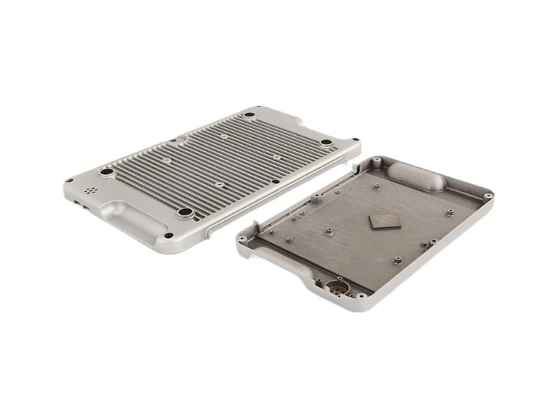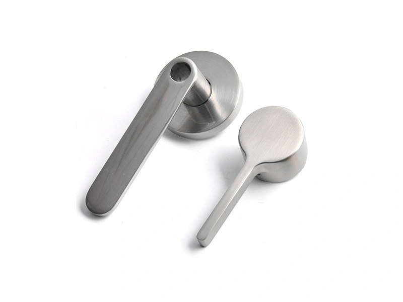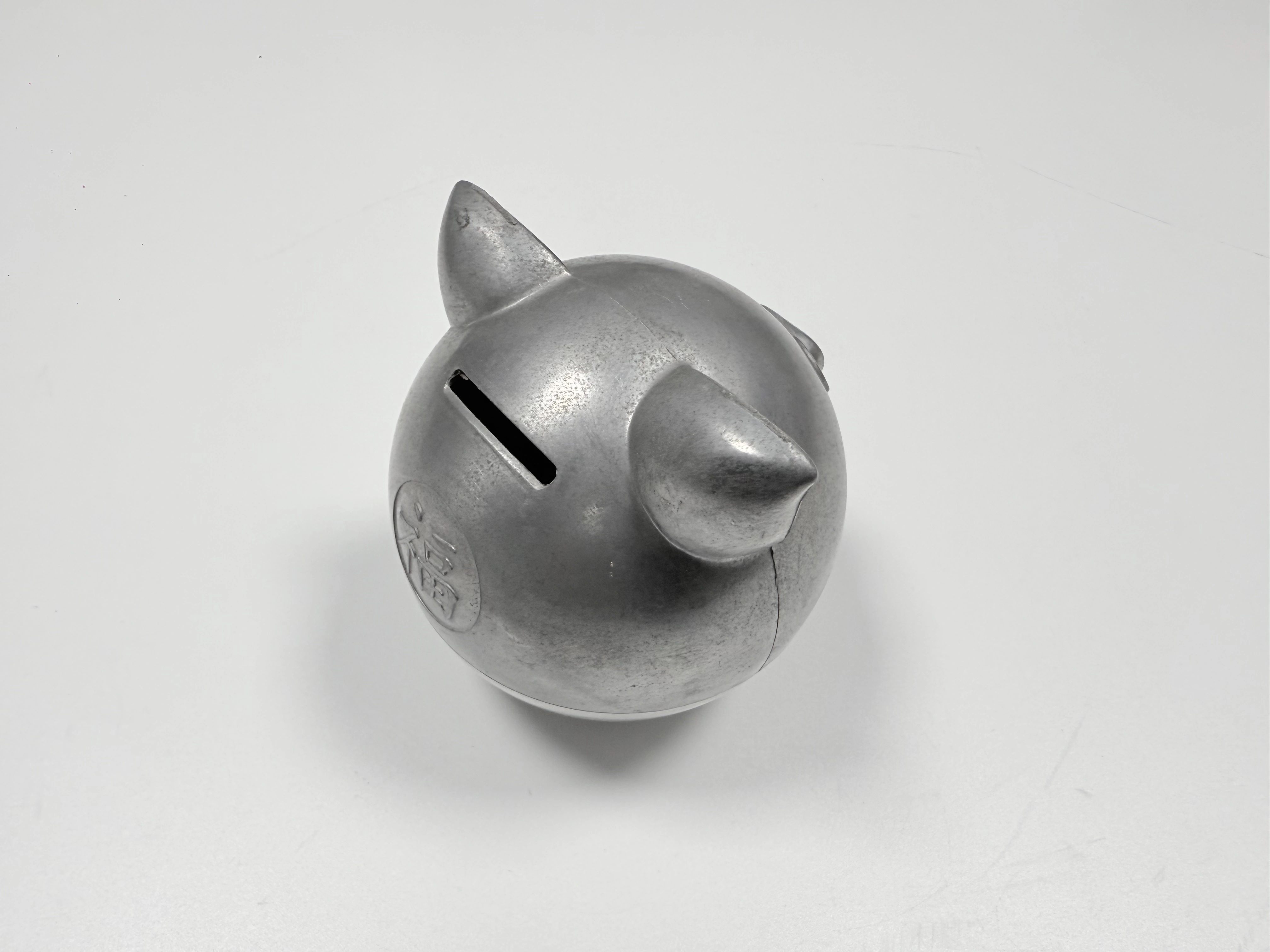
Can Zamak 5 Be PVD Coated?
Yes, Zamak 5 can take a PVD coating. The alloy is not the limit. The limit is the surface it arrives with and the layer stack underneath the top film. A zinc die casting that reaches Ra 0.5 with no open porosity, masked at the right faces, runs through a decorative PVD line without drama. One that arrives with a pit at the gate or a polished edge rounded by 0.1 mm will fail, and the coating step will not fix it.
Short Answer
Zamak 5 (ASTM B86 AC41A) is a standard substrate for decorative PVD on zinc die castings. The process runs at a substrate temperature around 120–150 °C, far below anything that moves the alloy, and deposits a 0.5–3 µm film.
The decision is not "can it be coated" but "is the surface and the stack right". Three conditions decide it: the polished surface, the absence of open pores, and a named layer system under the top film.
Why the Substrate Decides
PVD is a line-of-sight deposition. Metal vapor reaches the surface, condenses, and copies what it lands on. It does not flow into a recess, level a scratch, or close a pore. Whatever geometry the polished surface has is the geometry the coated part keeps.
That makes the substrate the controlling variable. Two parts from the same die can pass or fail depending on how the visible face was polished and whether a pore was opened at the gate. The coater sees the result, not the cause.
Ra 0.5 and Rz 2–4
Ra 0.5 µm is an arithmetic average. It can read 0.5 while the surface still carries 6 µm peaks. Rz is the number that describes those peaks, and the film is thinner than the peak-to-valley distance at the top of the range.
The working pair is Ra 0.5 with Rz 2–4. A surface that meets Ra but sits at Rz 6 will show scratches after coating, because the film follows the valleys and leaves the peaks exposed. The drawing should carry both numbers, not one.
What the Film Cannot Hide
An open pore 20 µm across is six to forty times the thickness of the film. The coating deposits on the pore wall as well as the face, so the pore stays a pore, and after coating it reads as a dark point under direct light.
The same applies to a cold shut line, a drag mark, and a rounded mating edge. Each is a geometry change, not a surface stain. If it is visible before coating, it will be visible after, usually more so because the film adds contrast.
The Layer Stack Under the Film
Decorative PVD on zinc is usually a stack, not a single layer. An electroplated copper/nickel underlayer levels the surface and carries corrosion resistance; the PVD top layer supplies color and wear resistance. With that stack, a masked face shows nickel, not bare zinc.
Direct PVD on zinc, without plating, is a different system. It can work for interior decorative parts with light service, but the corrosion protection and the color range are not the same. The drawing has to name the stack: plating thickness, top-layer thickness, and which faces are masked. "PVD" alone does not define what sits under the top film.
What to Put on the Drawing
A usable callout has four lines: substrate and condition, pre-coat finish (Ra and Rz), layer stack with thicknesses, and masked faces. Add the acceptance tests: adhesion to ASTM D3359 at 4B–5B, and neutral salt spray to ASTM B117 for 48 hours.
Callout | Value | Why it matters |
|---|---|---|
Substrate | Zamak 5, ASTM B86 AC41A, as cast | Sets the temperature window |
Pre-coat finish | Ra 0.5, Rz 2–4 | Film copies the profile |
Layer stack | Cu/Ni plating + PVD top, thicknesses named | Decides corrosion and color |
Masked faces | Mating faces, thread, coin slot | Decides what shows at the seam |
Adhesion | ASTM D3359, 4B–5B | Pass or fail, no opinion |
Corrosion | ASTM B117, 48 h | Separates stacks, not colors |
For the coating side in more detail, see PVD on zinc die castings; for the process window, see PVD coating.