English

What are the strongest materials available for 3D printing?

Table of Contents
Define What Strong Means for the Part
Candidate Families Have Different Advantages
Printing Changes the Property Set
Surface and Geometry Often Control Failure
Environment Can Reorder the Shortlist
Evidence to Request Before Release
Buyer Decision

There is no single strongest material for 3D printing. Metal alloys such as precipitation-hardening stainless steel, titanium alloys and some tool or nickel alloys can be strong candidates for high-load parts. Reinforced engineering polymers can be better when low mass and stiffness are the priorities, while tough unfilled polymers may survive impact or repeated flexing better than a brittle, higher-strength grade. The correct answer depends on how the part can fail, its build direction, operating environment and final post-processed condition.

Define What Strong Means for the Part

Start with the response that controls the design. Tensile strength addresses failure under a particular pulling test. Yield behavior indicates when permanent deformation begins. Stiffness controls deflection. Toughness and notch sensitivity matter in drops and impacts. Fatigue governs repeated loads, while creep governs deformation under sustained load, especially for polymers at elevated temperature. A lightweight moving arm may be judged by specific stiffness; a clip may need strain capacity; a tooling insert may need hardness and wear resistance.

That definition changes the shortlist. A nominally high-strength, low-ductility photopolymer can fracture at a screw boss during assembly. A fiber-filled polymer can keep a fixture stiff but fail at an unfavorable layer boundary. A metal part can carry high static load yet remain vulnerable to fatigue initiation at rough as-built surfaces. Do not accept the word strong without the load case, allowable deformation, cycles, temperature and failure criterion.

Candidate Families Have Different Advantages

Material-process familyWhere it may be a strong candidateWhat can overturn the choice
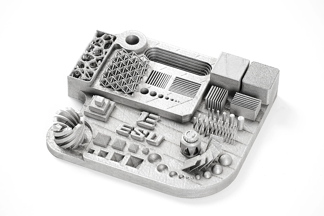
Laser powder-bed metalHigh stiffness, metallic temperature behavior and compact load pathsSurface-driven fatigue, residual stress, support scars and machining access
Short-fiber polymerStiff, lightweight fixtures, brackets and tooling aidsDirectional behavior, reduced ductility, moisture and insert loads
Continuous-fiber polymerSelected load paths that can follow planned reinforcementUnreinforced directions, fiber termination and geometric access
Tough unfilled polymerImpact, compliant features and damage-tolerant housingsCreep, temperature, chemicals and layer adhesion
Engineering photopolymerDetailed parts under a narrow, validated dutyAging, cure state, notches and environmental exposure

Within each row, exact grades still differ. A stainless alloy selected for corrosion resistance does not automatically outrank a titanium alloy on weight, or a tool steel on hardness. A carbon-filled nylon is not automatically tougher than unfilled nylon. The matrix identifies questions; supplier data and project tests decide the route.

Printing Changes the Property Set

The purchasable engineering entity is a material plus process, orientation and final condition. In extrusion, bead direction and interlayer fusion affect the load path. Polymer powder-bed parts have their own orientation, thermal-history and moisture effects. Vat resins depend on wash and cure schedules. Metal powder-bed parts may change through stress relief, heat treatment, hot isostatic pressing when specified, support removal and machining.

Coupon values can mislead when they come from a favorable direction or a section unlike the part. A vertical boss, thin wall, threaded insert and machined hole each create local behavior not shown by a generic tensile bar. For projects reviewed under a controlled 3D printing process, ask the supplier to identify the exact build and post-process state behind every property used in the design.

Surface and Geometry Often Control Failure

Notches, sharp wall transitions, unsupported down-facing surfaces and support-removal marks concentrate stress. Internal channels can retain powder and can be difficult to inspect. A coarse metal surface can shorten fatigue life even when bulk coupon strength is high. Sanding a polymer can expose filler or reduce a thin section; machining a metal can improve a bearing seat while changing the remaining wall.

Design the comparison around representative features. Include the smallest loaded wall, the real hole edge distance, the selected insert, and the transition most likely to crack. If a precision surface needs post-machining, test the machined condition rather than approving an as-built coupon and assuming the conclusion transfers.

Environment Can Reorder the Shortlist

Temperature, moisture, UV exposure and chemicals can reorder a room-temperature ranking. Polymers may soften, creep, absorb moisture or become brittle. Metals may oxidize, pit or lose fatigue resistance in a corrosive environment. Contact between dissimilar metals can add galvanic risk. Cleaning solvents can cause stress cracking in a polymer that passed a dry tensile test.

Use the actual concentration, temperature, contact time and applied stress when screening compatibility. Test after conditioning, not only immediately after printing. For intermittent heat, reproduce the cycle and inspect retained dimensions and function; for sustained load, include dwell time. The related guidance on high-temperature and chemical-resistant 3D printing explains why a single temperature or chemical-resistance label is insufficient.

Evidence to Request Before Release

Ask for material designation and lot control, process and machine family, build orientation, thermal or cure cycle, surface condition and any machining or coating. Request data in relevant directions and conditions. Then choose tests that represent the design: stiffness under load, insert pull-out, impact, fatigue, creep, leak, pressure proof, wear or environmental conditioning. Not every part requires every test; consequence and uncertainty set the scope.

Use witness coupons for process monitoring, but qualify critical geometry with a representative article. Record the acceptance limits before testing. If the winning route changes supplier, machine, orientation, feedstock or heat treatment, review whether the existing evidence remains applicable. The strongest available option is the one that meets the defined duty with controlled evidence, not the material with the largest isolated number on a datasheet.

Buyer Decision

Send the CAD model, load cases, critical directions, environment, life target, dimensional interfaces and required tests with the RFQ. Invite suppliers to propose more than one route and state the basis for each proposal. Compare accepted-part cost after supports, heat or cure treatment, machining, finishing and inspection. This method may select metal, reinforced polymer or unfilled polymer; importantly, it makes the word strongest traceable to the part's real job.

Copyright © 2026 Diecast Precision Works Ltd.All Rights Reserved.