How do anodized extrusion and die-cast aluminum differ visually?
While both are aluminum and can be anodized, the underlying manufacturing processes of extrusion and die-casting impart distinct visual characteristics that remain visible even after a high-quality anodized finish. The primary visual differences lie in surface texture, seam lines, and sharpness of detail.
Manufacturing Process: The Root of Visual Differences
The visual identity is dictated by how the raw aluminum part is created before it ever reaches the anodizing tank.
The Nature of Extruded Aluminum
Extrusion involves forcing heated aluminum billet through a shaped die, much like squeezing toothpaste. This process creates long, continuous profiles with a very consistent cross-section. The visual hallmarks are:
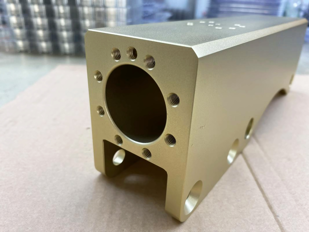
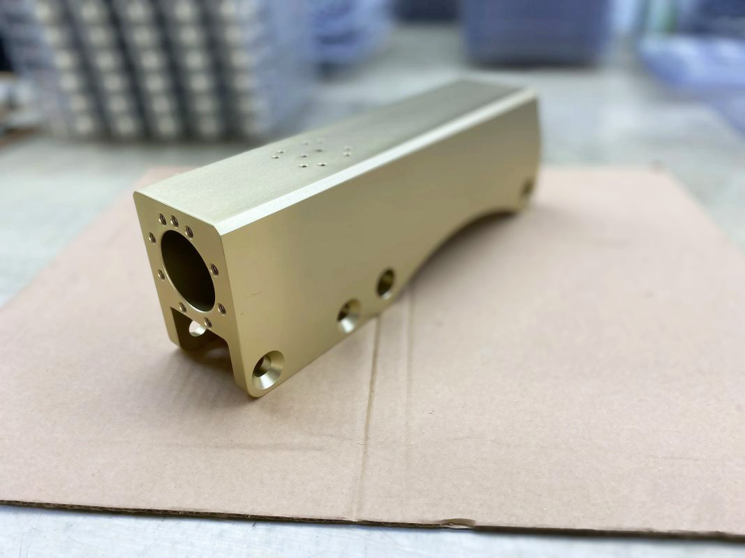
Consistent Grain/Lines: Often visible in the direction of extrusion, giving a slightly linear, "brushed" texture even before finishing.
Smoother Initial Surfaces: The die and the process itself can produce very uniform, flat surfaces.
Visible Seams: The anodizing process for extrusions does not create parting lines, but the extrusion itself is seamless by nature.
The Nature of Die-Cast Aluminum
Die Casting involves injecting molten aluminum under high pressure into a steel mold (or "tool") consisting of two or more halves. The visual hallmarks are inherent to this molding process:
Parting Lines: A fine, raised line is present where the two halves of the mold met. This is a definitive visual signature of any die-cast part.
Ejector Pin Marks: Small circular or rectangular marks on the non-cosmetic surfaces where pins pushed the solidified part out of the mold.
Potential for Subtle Texture: The mold surface can be textured (e.g., grain, bead-blasted), and this texture is replicated perfectly onto the aluminum surface.
Surface Treatment: How Anodizing Affects the Look
The Anodizing process amplifies these underlying differences because it is a transparent conversion coating that follows the substrate's topography.
Color and Reflectivity Consistency
On Extrusions: The uniform, homogeneous microstructure of extruded aluminum typically allows for extremely consistent color and reflectivity after anodizing. It is the preferred choice for large, flat, cosmetic panels where a perfectly uniform appearance is critical.
On Die Castings: The visual consistency can be slightly more variable. Factors like the flow of molten metal during injection can create subtle variations in the microstructure. Higher silicon alloys like A380 can result in a slightly mottled or "speckled" appearance under certain anodizing conditions, especially with clear or lighter colors, due to the silicon particles.
Highlighting Detail and Texture
On Extrusions: Anodizing will highlight the directional grain, resulting in a sleek, linear aesthetic. Sharp, crisp corners are easily achieved.
On Die Castings: Anodizing will faithfully reproduce any texture from the mold tooling. It will also make the parting lines and ejector pin marks more visible, not less, as these are physical features on the part's surface.
Materials: The Alloy's Influence
The aluminum alloy used plays a significant role in the final visual outcome.
Extrusion Alloys: Typically are from the 6xxx series (e.g., 6061, 6063). These are alloys with excellent anodizing characteristics, resulting in a clear, bright, and uniform surface that takes dye very well.
Die Casting Alloys: Are typically from the 3xx series (e.g., A380, A360) or A356 for high integrity parts. The higher silicon content, while excellent for casting, can give the anodized surface a darker, slightly grayish base color compared to an extrusion alloy.
Industries: Application-Based Visual Cues
You can often identify the process based on the product's form and finish.
Anodized Extrusion is Typical In:
Architectural frameworks (window, door, and curtain wall systems).
Sliding tracks and rails.
Consumer electronics frames and heat sinks.
Visual Cue: Long, straight, constant cross-sections with no parting lines and a very uniform, consistent color.
Anodized Die Casting is Typical In:
Automotive components like sensor housings.
Visual Cue: Complex, three-dimensional shapes with visible parting lines and often a molded-in texture to hide flow lines.
Conclusion
In summary, while both processes yield durable anodized aluminum parts, extrusions offer a more uniform, linear, and seamless visual appearance, ideal for long, straight components. Die castings provide the visual signature of complex 3D shapes but will always show subtle evidence of their molding process through parting lines and potential slight color variation due to their alloy composition. The choice is a trade-off between geometric freedom and achieving absolute visual perfection on large, flat surfaces.