How Do Type 1 and Type 2 Anodize Affect Aluminum Part Dimensions?
How Do Type 1 and Type 2 Anodize Affect Aluminum Part Dimensions?
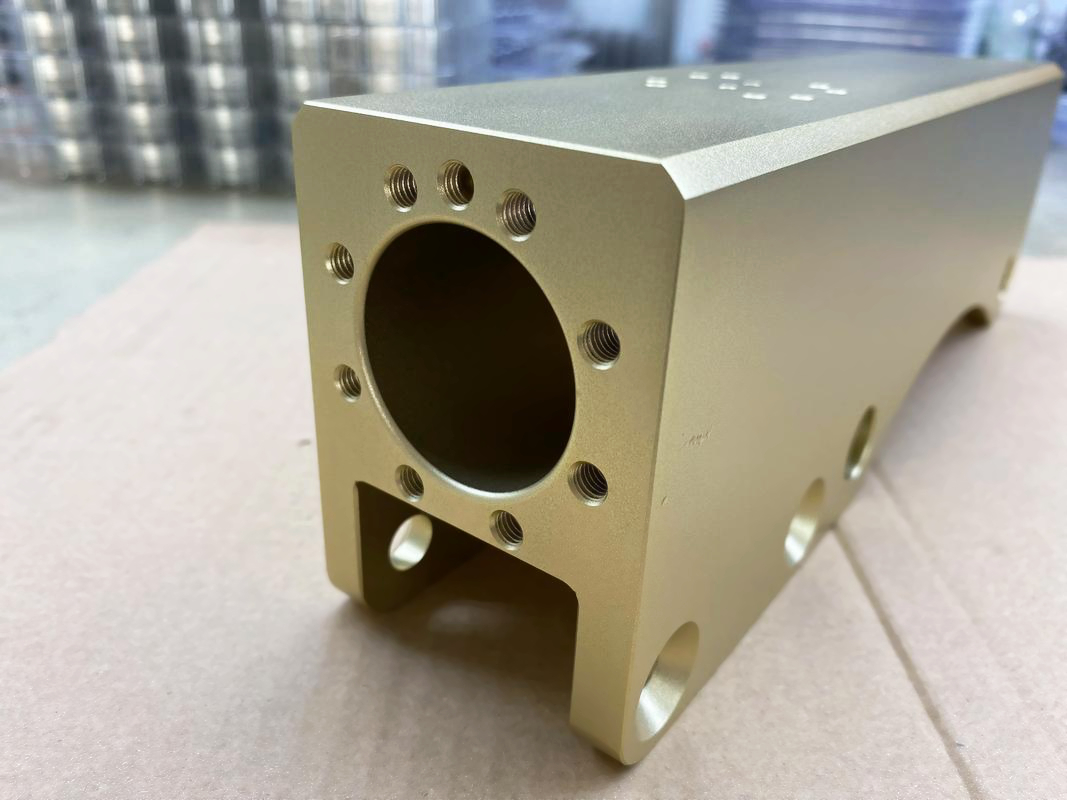
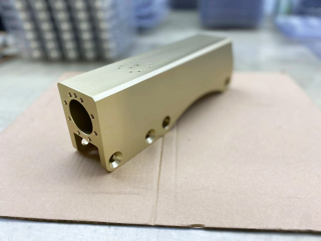
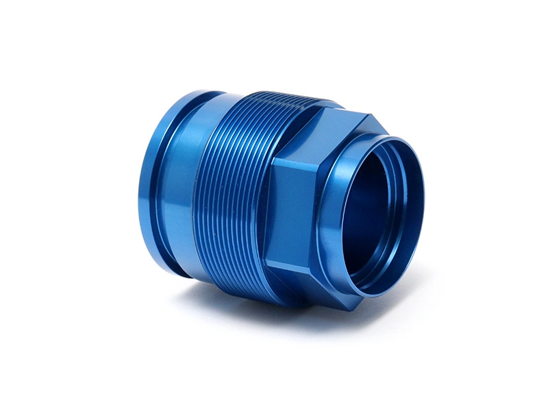
Type 1 and Type 2 anodize affect aluminum part dimensions by adding an oxide layer to the surface. Type I is usually thinner and has lower dimensional impact, while Type II is usually thicker and may affect small holes, threads, close fits, sliding features and mating surfaces. Buyers should define whether critical dimensions apply before or after anodizing.
Type I is often discussed around 2 to 7 microns, while Type II is often discussed around 5 to 25 microns. The actual dimensional change depends on alloy, process and coating thickness because anodizing grows partly inward and partly outward. Buyers should not assume every feature changes by the same amount without supplier confirmation.
The thinner Type I coating can be useful when dimensional change must be minimized. Type II can still be controlled, but it requires more attention on tight features. If the part has only broad visible surfaces, dimensional impact may be minor. If the part has precision holes or threaded features, masking or compensation may be needed.
For dimension-sensitive parts, buyers can review hard anodizing dimensional change principles and specified anodic film thickness effects.
Dimension-Sensitive Features
Feature | Risk | Buyer Action |
|---|---|---|
Threaded holes | Gauge fit may change after anodizing | Mask, define final thread condition or approve chase operation |
Dowel holes | Pin fit may become too tight | Mask or define final coated hole size |
Bores | Diameter may reduce after coating | State final dimension after anodizing |
Sliding slots | Clearance can shrink and create friction | Review Type II thickness and clearance |
Electrical contact points | Anodize is insulating | Mask grounding or contact surfaces |
Sealing surfaces | Surface condition and thickness may change contact | Confirm whether coating is allowed on the face |
Drawing notes should make dimensional responsibility clear. If all dimensions apply before anodizing, the supplier should know. If selected dimensions apply after anodizing, those dimensions should be marked. Confusion between pre-finish and post-finish dimensions is a common cause of rejected parts.
Masking is useful when a feature cannot accept coating. However, masking must be planned early because it affects cost and process. A thread or bore may be masked, but the edge of the masked area should also be acceptable after finishing. Buyers should not assume masking is included unless it appears in the RFQ.
Type I is often chosen when lower dimensional change is part of the reason for the finish. Even then, the buyer should not ignore critical features. Small holes, close-fitting pins and electrical contact points may still need masking or inspection. The thinner coating reduces risk, but it does not eliminate the need for drawing clarity.
Type II creates a larger planning issue because buyers often use it on commercial parts with both appearance and assembly requirements. A black anodized cover may look correct but fail if screw threads are tight, a dowel hole is undersized after coating or a grounding pad is accidentally anodized. These are not cosmetic defects; they are finish-driven functional failures. The RFQ should therefore list fit-critical features separately from visible surfaces.
Inspection After Anodizing
Inspection should happen in the condition that matters. If final fit is after anodizing, the critical hole, thread or bore should be checked after anodizing. Measuring before coating does not prove final assembly. If a surface is masked, the mask result should be inspected as part of finish approval.
Buyers can reduce risk by using a first article. A small initial batch can confirm whether Type I or Type II thickness affects the part before a larger order is processed. If parts fail fit after anodizing, the correction may require machining, masking or drawing changes.
For Type II, first article approval is especially useful when color and fit both matter. The buyer can check whether the part assembles correctly and whether the finish matches the visual standard. If the coating creates a fit problem, the next step may be to adjust pre-coating machining size or add masking.
Practical Drawing Note Example
A practical drawing note may state that dimensions apply after anodizing except for masked threads, or it may mark only selected bores as final coated dimensions. The exact wording should match the buyer's quality system, but the principle is the same: the supplier should know which dimensions are checked after finish and which areas must remain uncoated.
Buyers can also use a feature table on the drawing. For example, threaded holes can be marked as masked, dowel holes can be marked as final size after finish, and cosmetic outside faces can be marked as anodized and sealed. That kind of note prevents a finishing supplier from treating every surface the same way. It also helps the machining supplier leave the correct allowance before the parts move to anodizing.
This is more reliable than relying on a general finish note hidden in the title block.
Neway can help buyers coordinate machining, anodizing and inspection so Type I or Type II anodize supports the part function without creating avoidable fit problems.