How Does Anodizing Thickness Affect Holes, Threads and Fits?
How Does Anodizing Thickness Affect Holes, Threads and Fits?
Anodizing thickness affects holes, threads and fits by changing the surface dimension of aluminum parts. Type 2 anodizing usually has a smaller dimensional effect, while Type 3 hardcoat anodizing can significantly affect bores, slots, threads, sliding clearances and mating surfaces. Buyers should define whether critical dimensions apply before coating or after coating.
Anodizing forms an oxide layer on the aluminum surface. Part of the layer grows inward and part grows outward, so the final dimensional change is not always equal to the full coating thickness added to each side. The exact result depends on alloy, process and thickness. For purchasing and drawing control, buyers should avoid guessing and instead mark critical coated dimensions clearly.
Type 2 anodizing is often discussed around 5 to 25 microns. Type 3 hardcoat is often discussed around 25 to 100 microns. Even small thickness changes can matter on tight features. A press fit, dowel hole, bearing bore, fine thread, sliding slot or sealing groove can fail if coating thickness was ignored.
For coating buildup risk, buyers can review how Type III hard anodizing changes part dimensions and how anodic film thickness affects pricing.
Features That Need Thickness Review
Feature | Thickness Risk | Buyer Action |
|---|---|---|
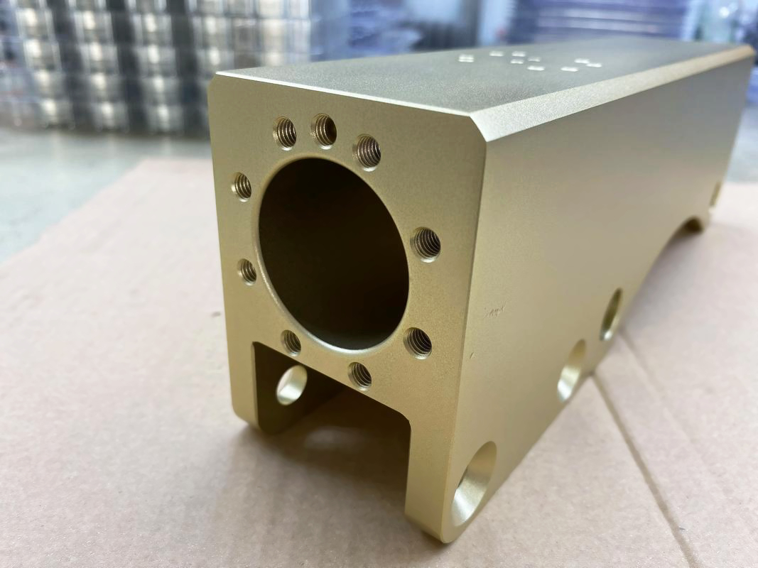
Threaded holes | Coating can tighten threads and cause gauge failure | Mask, adjust pre-coating thread, or define post-coating thread requirement |
Bearing bores | Diameter may become too small for bearing installation | Define final coated bore size and inspection method |
Dowel holes | Locating pins may not fit after coating | Mask or machine allowance into the hole size |
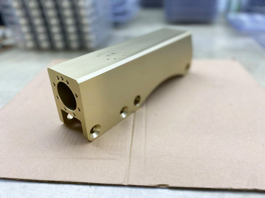
Sliding slots | Clearance may shrink and create friction | Increase design clearance or coat only selected surfaces |
Sealing grooves | Groove width or depth may change gasket compression | Define whether coating is allowed in the groove |
Electrical contact points | Anodizing is insulating and may block conductivity | Mask contact areas if electrical connection is needed |
Masking is often the simplest solution for features that cannot tolerate coating. Threads, electrical contact areas, precision bores and grounding points may be masked before anodizing. However, masking also adds cost and process planning. The buyer should mark these areas clearly on the drawing so the anodizing supplier does not guess.
Pre-machining compensation is another solution. If a bore must be anodized and still meet final size, the machining process may leave it slightly larger before coating. This requires coordination between machining and anodizing. If the machine shop and anodizer are separate suppliers, the buyer must control the final dimension requirement carefully.
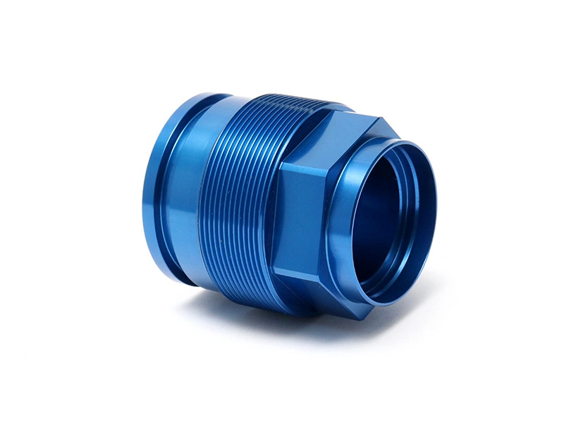
Buyers should be especially careful with internal threads. If the thread is anodized, pitch diameter and gauge fit can change. If the thread is masked, the mask boundary must be controlled so coating does not create rough edges around the opening. If the thread is chased after anodizing, the buyer should confirm whether removing coating from the thread is acceptable for corrosion or wear requirements.
How to State Anodized Dimensions on a Drawing
Buyers should state whether dimensions are before anodizing or after anodizing. A note such as "dimensions apply after anodizing unless otherwise specified" can be useful, but only if the supplier understands which features are critical. For Type 3 hardcoat, it is safer to mark the most sensitive holes, threads and sliding surfaces individually.
Inspection should match the requirement. If the final coated bore size matters, the bore should be inspected after coating. If a thread is masked, the masking result and thread gauge should be checked after finishing. If an electrical contact area is masked, continuity or surface exposure may need confirmation.
The same logic applies to sliding features. A rail or slot should not be accepted only by coating thickness. The final part should be checked against the mating component or a functional gauge when possible. A coating can be within thickness range but still create too much friction if clearance, surface texture or edge condition was not planned.
Drawing Notes That Reduce Fit Risk
Useful drawing notes identify masked features, final coated dimensions, coating thickness range and surfaces where coating is optional or prohibited. For Type 3, buyers may also mark wear surfaces separately from general surfaces. This helps the supplier avoid coating areas that should remain bare while still protecting the surfaces that need hardcoat performance.
Buyers should also specify inspection timing. A bore measured before coating does not prove final fit after anodizing. A thread checked before masking does not prove the final thread after finishing. Final inspection should match the finished condition that the assembly will use.
Neway can coordinate anodizing requirements with machining and inspection so buyers do not discover fit problems after parts are coated. This is especially important when Type 3 hardcoat anodizing is used on precision aluminum parts with close assembly relationships.
For high-risk parts, a coated first article should be assembled with the mating component before the finish is released for a larger order.
This prevents a correct coating from becoming an assembly failure.