How Thick Is Type II Anodizing and How Does It Affect Fit?
How Thick Is Type II Anodizing and How Does It Affect Fit?
Type II anodizing is often discussed around 5 to 25 microns, but the exact thickness depends on the drawing, standard, alloy, supplier process and required finish. Buyers should not treat the range as a universal guarantee. The RFQ should state the required thickness or reference the applicable standard so the supplier can quote and inspect the correct finish.
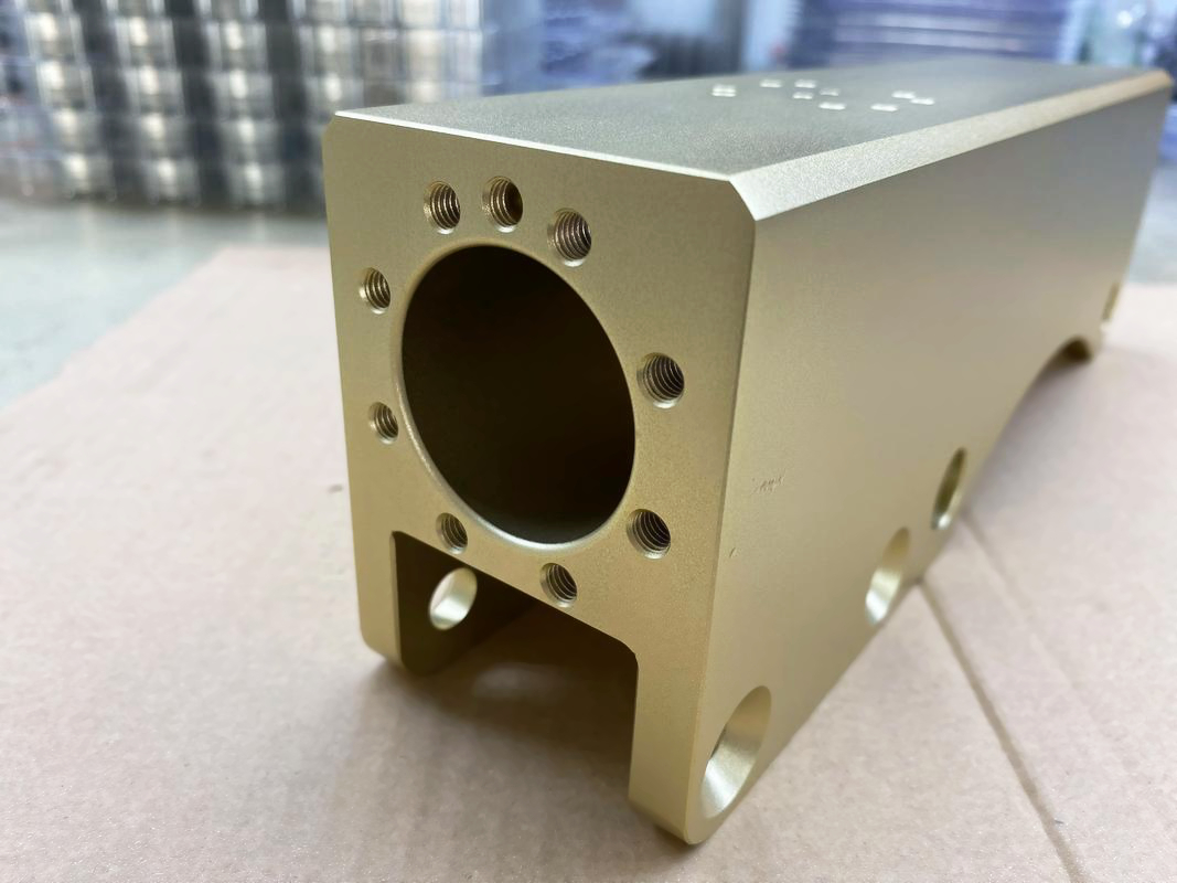
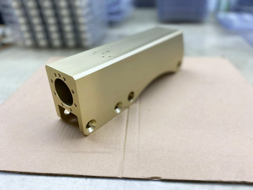
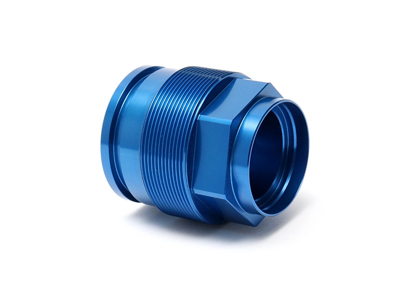
Type II is usually thinner than Type III hardcoat, but it can still affect fit. Anodizing creates an oxide layer on the aluminum surface. Part of the oxide grows inward and part grows outward, so holes, threads, slots and mating surfaces can change after finishing. The effect may be small on broad surfaces but important on precision features.
For buyers, the practical question is whether dimensions apply before anodizing or after anodizing. If a bore, dowel hole or sliding slot must function after finishing, the drawing should define final coated dimensions or masking. If the part is inspected only before anodizing, assembly problems may appear later.
For fit-sensitive coating review, buyers can compare specified anodic film thickness effects and hardcoat dimensional change principles.
Features Affected by Type II Thickness
Feature | Potential Effect | Buyer Control |
|---|---|---|
Threaded holes | Gauge fit may tighten after coating | Mask threads or define post-finish thread condition |
Dowel holes | Pin fit can become too tight | State final coated diameter or mask hole |
Bearing bores | Diameter and contact condition may change | Review machining allowance and inspection |
Sliding slots | Clearance may reduce | Confirm slot width after coating |
Grounding pads | Anodize is electrically insulating | Mask contact surface |
Sealing faces | Surface condition may affect gasket contact | Define whether coating is allowed |
Why Masking Is Often Needed
Masking protects features that cannot accept coating. Even a Type II coating can be too much for a tight pin hole or electrical contact point. Masking also protects sealing faces, threaded holes and selected machined datums. The buyer should mark masked features on the drawing rather than relying on the anodizing supplier to guess.
Masking adds cost and handling steps, but it can prevent much larger problems. A part that is cheaper to anodize without masking can become expensive if threads need chasing, holes need rework or grounding surfaces fail in assembly. Masking should be treated as part of the finished-part specification.
Inspection After Type II Anodizing
Inspection should match the part function. If the coating thickness is critical, a thickness check should be required. If a hole or thread is critical, it should be inspected after anodizing or clearly masked. If a visible face is cosmetic, inspection should include color and surface condition. Checking only raw machined dimensions does not prove the anodized part will work.
A first article is useful when the project has tight features. The first finished samples can confirm whether Type II thickness affects assembly, whether masking is correct and whether the finish meets visual expectations. If a problem appears, the buyer can adjust machining size, masking or drawing notes before a larger batch is anodized.
Buyers should also decide whether a feature is better masked or dimensionally compensated. Masking may be best for grounding pads, threads and sealing faces that should remain bare. Size compensation may be better for a feature that must be anodized but still meet a final fit. The correct choice depends on the function of the feature and whether coating is allowed on that surface.
Drawing Notes That Reduce Fit Risk
Helpful drawing notes separate pre-finish and post-finish requirements. A drawing may state that all dimensions apply before finish except selected bores that must meet final coated size. It may also identify masked threaded holes, uncoated grounding pads and cosmetic anodized faces. These notes prevent the machining supplier and finishing supplier from making different assumptions.
For production parts, buyers should keep the same drawing revision, masking instruction and inspection method across repeat orders. If a later order changes thickness, sealing or masking, the fit should be rechecked. A small finish change can become a functional change when the part contains precision features.
Example of Type II Fit Planning
A machined 6061 mounting block may have black Type II anodizing on the outside faces, four tapped holes and two dowel holes. The outside faces can be anodized for appearance, the tapped holes can be masked or checked with a thread gauge, and the dowel holes can be controlled as final coated dimensions. By marking these features before quotation, the buyer avoids rework after the finish is applied.
If the same part later moves into repeat production, the approved masking diagram and inspection gauges should stay with the production record.
Neway Support for Type II Fit Control
Neway can coordinate CNC machining, masking, Type II anodizing and inspection so critical features remain usable after finishing. The best Type II plan defines final coated dimensions before parts leave machining, not after assembly fit has already failed.