How Can Custom Die Casting Parts Be Designed for Reliable Manufacturing?
How Can Custom Die Casting Parts Be Designed for Reliable Manufacturing?
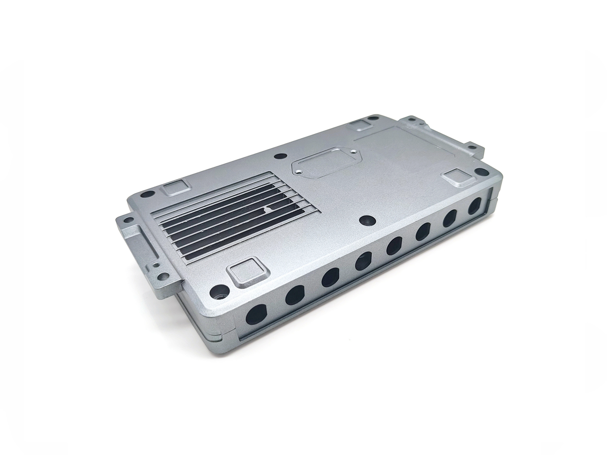
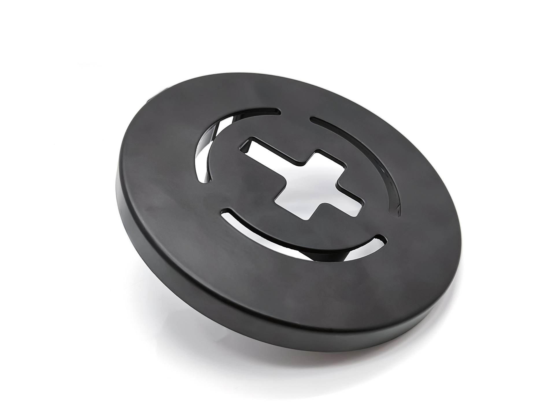
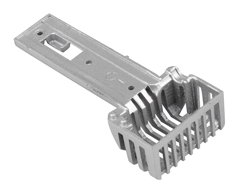
Custom die casting parts can be designed for reliable manufacturing by controlling wall thickness, draft angles, ribs, bosses, fillets, parting lines, gate locations, machining allowance, surface finish areas and assembly interfaces before tooling begins. Good design reduces shrinkage, porosity, deformation, flash, cosmetic defects and assembly failure.
1. Why Design Review Should Happen Before Tooling
A 3D model may show the final part shape, but it may not fully show whether the part is suitable for die casting. If the design has uneven wall thickness, sharp corners, thick bosses, thin ribs, hidden cosmetic surfaces or unclear machined areas, problems may appear during trial casting or sample approval.
Before tooling, buyers should request die casting design review and engineering support for die cast parts. This helps connect product design with material, mold, machining, surface finishing and inspection requirements.
Design Factor | Manufacturing Risk | Planning Method |
|---|---|---|
Uneven wall thickness | Shrinkage, porosity or filling instability | Optimize wall transitions and avoid sudden thickness changes. |
Sharp corners | Stress concentration and filling issues | Add suitable fillets to improve flow and reduce stress. |
Bosses and ribs | Sink marks, deformation or internal defects | Balance strength, wall thickness and casting feasibility. |
Cosmetic face | Visible tooling marks, gate marks or ejector marks | Plan parting line and ejector locations before mold design. |
Machined areas | Insufficient stock for post-machining | Add machining allowance and mark functional surfaces. |
Assembly interface | Fit failure or unstable positioning | Define datum surfaces and critical dimensions early. |
2. How Wall Thickness, Draft, Ribs and Bosses Affect Quality
Wall thickness affects filling, solidification and shrinkage. Uneven sections may create porosity or deformation, while very thin areas may not fill properly. Draft angles help parts release from the mold smoothly. Fillets help reduce stress concentration and improve metal flow.
Ribs and bosses should support strength without creating heavy local sections. If bosses are too thick or ribs are poorly connected, the part may develop sink marks, internal defects or deformation. Neway can help buyers improve manufacturable die cast part design before tooling.
3. How Tooling Layout Affects Appearance and Function
Tooling layout affects parting lines, gate locations, ejector marks, surface quality, filling behavior and long-term production consistency. If cosmetic surfaces are not defined early, tooling marks may appear on visible faces. If gate or ejector locations conflict with functional areas, additional rework may be required.
Tooling for custom die casting parts should be reviewed with part function, surface finish, machining allowance and assembly needs. For complex parts, mold flow analysis for die casting precision can help evaluate filling and defect risk before mold manufacturing.
Design Risk | Possible Result | Recommended Control |
|---|---|---|
Drawing only considers outer shape | Casting defects, post-machining conflicts or finishing issues may appear. | Run DFM review before tooling. |
Functional areas are not marked | Critical dimensions may not be controlled. | Define datum surfaces, machined areas and inspection points. |
Machining allowance is missing | Post-machining may not correct functional features. | Add machining allowance before mold design. |
Cosmetic faces are not defined | Parting lines or ejector marks may appear on visible areas. | Mark visible surfaces before tooling layout. |
Tooling starts without manufacturability review | Repeated mold modification and delivery delays may occur. | Review design, material, tooling, machining and finishing together. |
4. How Neway Reduces Tooling and Sampling Risk
Neway can help buyers review custom die casting parts before tooling by checking material suitability, geometry, wall thickness, cosmetic surfaces, post-machining needs, finish requirements and assembly interfaces. This early review helps reduce trial mold rework, sample delays and production instability.
Summary
Buyer Concern | Recommended Design Action |
|---|---|
Will the part cast correctly? | Review wall thickness, draft angles, ribs, bosses, fillets and mold flow risk. |
Will functional areas meet requirements? | Define critical dimensions, machined surfaces, datum features and inspection points. |
Will visible surfaces look acceptable? | Mark cosmetic faces and review parting lines, gates and ejector marks. |
When should DFM review happen? | Before tooling, not after trial casting problems appear. |