How Should Cosmetic Defect Zones Be Graded on a Powder-Coated Casting?
Cosmetic defect zones should be graded by visibility, customer interaction and product orientation, then linked to defined viewing conditions and approved defect limits. A surfaces are normally prominent during use, B surfaces are visible only from secondary angles or during handling, and C surfaces are hidden after assembly. The exact labels and limits belong to the buyer's drawing and finish standard.
Zone grading does not override function. A hidden C surface around a gasket, electrical contact or corrosion-critical edge can need stricter functional control than a visible A surface. Cosmetic and functional maps should therefore be separate but coordinated.
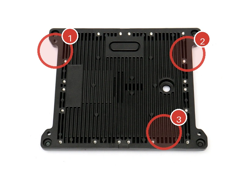
How to Draw A, B and C Surface Zones
Use marked drawing views or photographs that show boundaries, normal product orientation and areas exposed after assembly. Define transition bands where a surface changes class. Avoid vague notes such as “visible surfaces must be perfect,” because inspectors and suppliers may view the part from different angles.
Zone | Typical Visibility | Control Direction |
|---|---|---|
A surface | Primary user-facing area in normal operation | Tight master, color, gloss, texture and defect limits |
B surface | Secondary angle, installation or routine handling | Defined but broader local appearance limits |
C surface | Hidden after assembly | Basic coverage unless function requires more |
Functional zone | Any visibility | Fit, seal, ground or protection overrides cosmetic class |
Transition band | Boundary between classes or mask edge | Specific blend, feather or overspray rule |
Which Viewing Conditions Should Be Controlled?
Define lighting type and intensity range where practical, viewing distance, observation time, orientation and whether magnification is allowed. A defect visible only under grazing inspection light at very close distance should not automatically be judged by the same rule as a mark visible during normal product use.
Color, gloss and texture need approved masters or instrument limits. Masters should represent production-intent substrate because cast texture affects appearance. The powder coating approval should record powder identity and master revision.
How Finish Masters Should Be Created and Maintained
A master should come from the approved production-intent casting, preparation and powder route. Label it with part revision, powder supplier and code, color, gloss or texture, approval date and protected storage condition. A flat color chip can support color communication but may not reproduce cast texture, edge flow or local gloss.
Store masters away from ultraviolet light, abrasion, chemicals and uncontrolled heat. Define when they expire or require comparison with a reference standard. Working masters used on the line can be replaced more frequently than a protected control master. Every replacement should be cross-approved rather than accepted because it looks close to the previous piece.
Digital photographs help training but are unreliable as the sole color standard because camera, screen and lighting alter appearance. Instrument limits can strengthen control, yet visual texture and local defects still need human comparison under the defined viewing method.
How to Write Defect Limits Without Creating a Vague Perfect Finish
Name observable conditions such as pinholes, craters, scratches, chips, exposed substrate, dirt inclusions, color variation and mask-edge irregularity. Define whether they are prohibited, limited by size and count, or accepted only outside an exclusion distance from edges and logos. Use representative photographs for conditions difficult to describe numerically.
Do not write the standard to hide substrate defects. A filled or textured surface can change visibility but cannot establish that a casting pit, crack or structural discontinuity is acceptable. Incoming casting standards remain separate from final appearance.
How Zone Grading Works in Production Inspection
Inspect the part in its defined orientation, then rotate only as the zone map requires. Record defect type and zone rather than one overall pass statement. Sampling can reflect risk and process history, but recurring defects should trigger containment even if individual counts remain near the limit.
Consider a hypothetical coated enclosure. The front face and top rim are A surfaces; side walls are B; the inner cavity is C; the gasket land and grounding pad are functional masked zones. A small texture variation accepted inside the cavity would not be accepted on the front face, while any powder on the grounding pad fails function regardless of appearance. The example is a grading model, not a Neway product result.
Broader decorative coating guidance for die cast parts can support finish selection, but the part-specific zone map remains the inspection authority.
Approval Item | What to Freeze |
|---|---|
Zone map | Views, boundaries and normal orientation |
Viewing method | Light, distance, time and magnification |
Finish master | Color, gloss, texture and substrate state |
Defect library | Names, limits and approved photo examples |
Functional override | Seal, fit, ground and protection requirements |
Change trigger | Powder, source, process or appearance-master revision |
A zone-based standard gives buyers stricter control where appearance creates value and practical control where the surface is hidden. It also reduces disputes by making the viewing condition, defect vocabulary and functional overrides explicit before production.