How accurate can complex sand-cast parts be after post-processing?
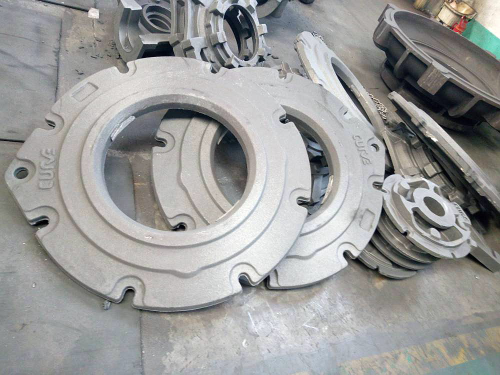
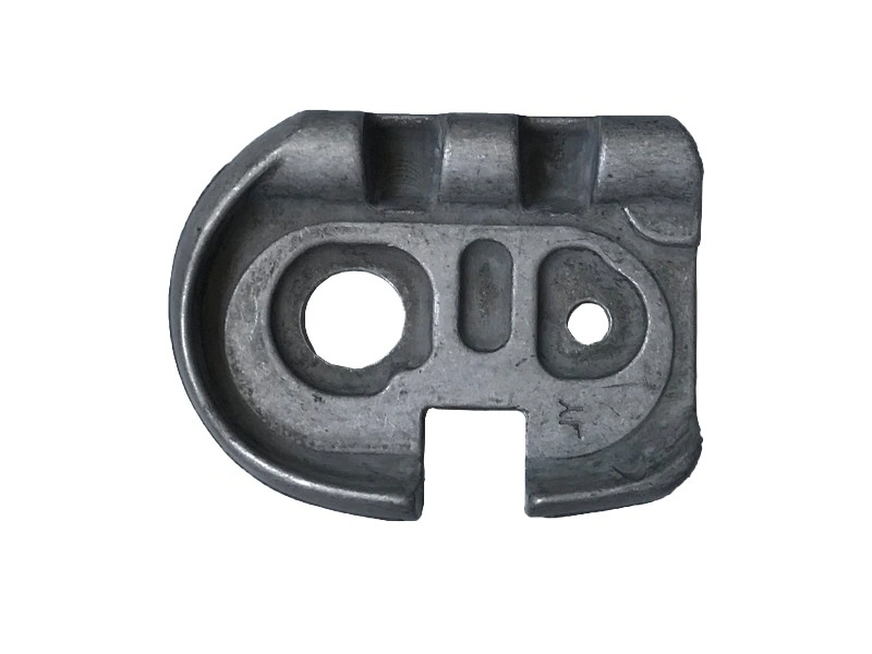
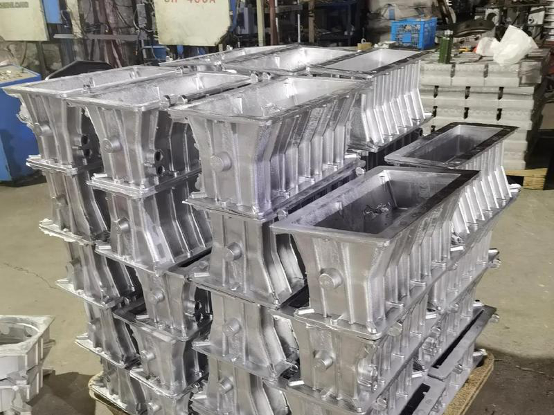
Complex sand-cast parts can achieve machining-level accuracy on selected post-processed features, but the achievable values are drawing-, feature- and supplier-specific. As-cast contours remain influenced by mold method, pattern or printed-sand accuracy, parting, core position, alloy contraction, section changes and distortion. Machine only the interfaces that require tighter control, and confirm tolerances after the supplier reviews geometry, datum access, stock and final condition.
Separate Five Dimensional Zones
Features formed within one mold half usually have a different error chain from those crossing the parting line. A dimension from mold surface to one core includes core location. A relationship between separate cores includes both locators and assembly. A machined feature adds rough-datum, fixture and cutting variation. A dimension after heat treatment or coating may include later movement or buildup.
Classify each important dimension by formation method. Then assign an as-cast tolerance, machining operation, process-development dimension or reference status. One general tolerance cannot describe all five zones on an intricate housing.
Build a Feature-Specific Accuracy Plan
| Feature type | Preferred delivered state | Planning concern | Acceptance evidence |
|---|---|---|---|
| Nonmating outside contour | As cast or cleaned | Parting, distortion and dressing | Profile/size check in named state |
| Core-formed passage | As cast, locally machined if accessible | Core shift and minimum wall | Location, continuity or wall check |
| Mounting or sealing plane | Machined | Cleanup stock and rough datum stability | Flatness/location from final datum |
| Bearing or alignment bore | Machined, possibly in a related setup | Tool access and relationship to passage | Size, form and position report |
| Coated interface | Machined/masked/finished as specified | Finish buildup and masking boundary | Measurement in delivered condition |
This matrix forces a decision about what the customer is buying. A scanned rough casting, an annealed blank and a coated machined part are different measurement states. The drawing and report must name the state so results are comparable.
Plan Machining Allowance Before Mold Release
Allowance must cover expected casting variation, distortion, setup and surface cleanup while protecting minimum walls. Too little stock leaves uncleaned areas; too much adds cutting, fixture load and residual-stress movement. Core-related surfaces can shift independently of the outside mold, so an allowance based only on external size may not protect a bore or passage wall.
Review stock by feature and direction. Show cast and finished geometry in the controlled model or drawing. The guidance for casting machining allowance should be applied before pattern compensation, core dimensions and first-operation targets are approved.
Establish Rough and Finished Datums
The first machining setup needs repeatable rough-casting contact. Intentional datum pads or targets may be added where they can be molded, cleaned and clamped. Avoid locating from irregular gate contacts, dressed parting flash or a thin flexible wall. Clamps should not distort the casting or load an internal discontinuity risk area.
Once primary surfaces are machined, later operations can use finished datums. If several bores or faces require a close relationship, consider machining them in one controlled setup or demonstrate the transfer method. When an external bore must align with a cored passage, define how the hidden passage location enters the datum strategy.
Sequence Thermal, Machining and Finishing Operations
Heat treatment, stress relief, rough machining and finish machining can change shape. The appropriate sequence depends on alloy, wall distribution, stock and tolerance. A large asymmetric casting may need an intermediate dimensional check before finish cuts. Do not promise final accuracy based only on machine capability while ignoring casting movement.
Blasting and gate dressing affect rough surfaces but do not create precision datums. Coatings or conversion treatments can change interface dimensions or surface contact, and masking transitions can create local edges. Specify whether final tolerances apply before or after finish and whether threaded, sealing or grounding zones are masked.
Inspect As-Cast and Machined Results Separately
As-cast inspection shows whether pattern/mold compensation, parting, core position and distortion leave a usable blank. Final inspection shows whether machining produced the required interfaces. Reporting only machined dimensions can hide low stock, unstable location or a core shift that threatens another wall.
Calipers, gauges, CMMs and optical or structured-light scanning suit different surfaces. Rough texture and free-state distortion influence contact and scan alignment. Internal geometry may need borescope, radiographic, CT, ultrasonic or destructive evidence depending on material and access. Every method needs a defined datum/alignment and known uncertainty relative to the tolerance.
Use First-Article Data Without Claiming Capability Too Early
Measure risk features on the first casting before and after relevant post-processing. If compensation, core location, fixture or sequence changes, issue a new revision and repeat affected checks. One conforming sample does not establish statistical capability across molds, pours, heat-treatment batches and machining setups.
For repeat low-volume work, collect data at the variation sources that matter and agree on sampling. The broader explanation of casting versus machining tolerances helps buyers avoid using a machine-tool specification as a whole-part casting promise.
RFQ for a Defensible Accuracy Answer
Send controlled CAD and drawing, exact alloy/final condition, mold and core concept if known, section map, datums, general and explicit tolerances, geometric requirements, minimum walls, machining zones, finish, free or restrained measurement state, inspection methods and report needs. Ask the supplier to mark achievable as-cast features, proposed machining, allowances, setups and exceptions.
The useful answer to "how accurate" is a feature-by-feature commitment in the named delivered state. Complex sand casting supplies the near-net form; controlled post-processing supplies selected precise relationships. Both must be engineered and measured together.