Can urethane casting simulate multiple materials or dual-durometer assemblies?
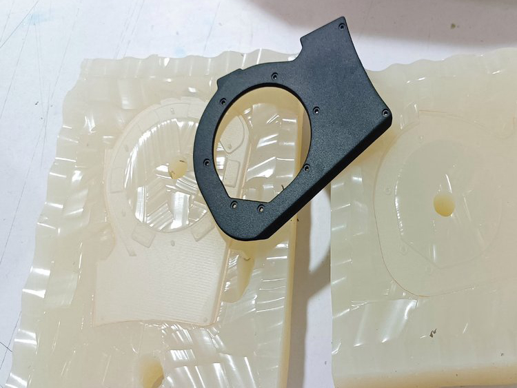
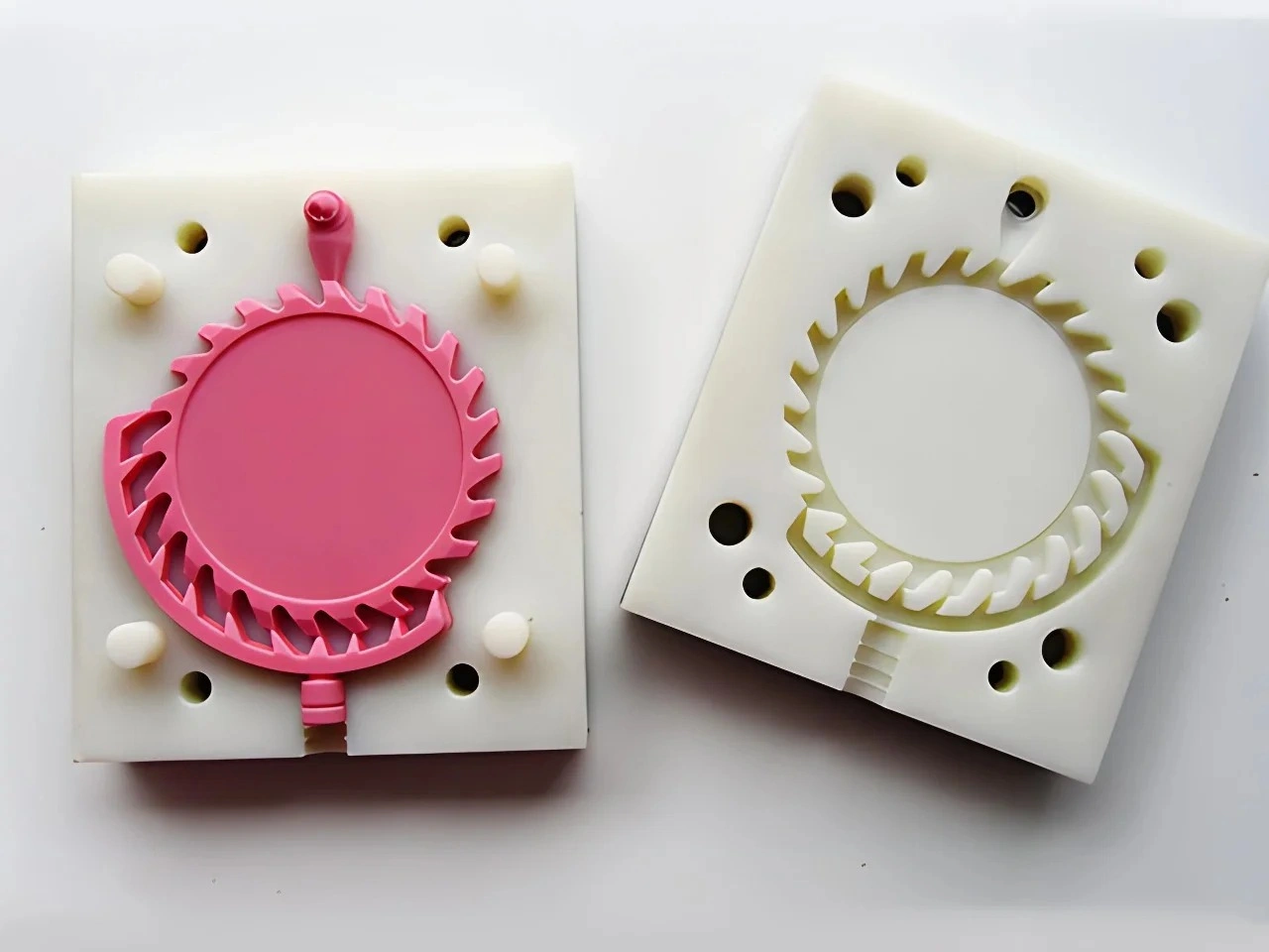
Yes. Urethane casting can simulate a multi-material or dual-durometer assembly by sequentially casting different polyurethane systems, casting around a prepared insert, or making separate rigid and flexible parts for assembly. It can help evaluate grip feel, seal geometry, color breaks, insert location and interface shape. It does not prove production overmold adhesion or exact thermoplastic behavior; the route and test must match the interface's actual job.
Choose the Interface Route
| Prototype route | Best use | Primary risk | Evidence to request |
|---|---|---|---|
| Sequential casting | Integrated soft-over-rigid regions and tactile evaluation | Incomplete bond, contamination, bleed or trapped air | Process identification, sectioned sample and functional interface test |
| Cast around hardware | Threaded inserts, magnets, pins or rigid carriers | Movement, leakage, poor encapsulation or local cracking | Location check plus pull, torque or leak test as applicable |
| Separate cast parts | Frequent material or geometry swaps and serviceable assemblies | Joint stack-up and unrealistic assembly method | Assembly record, gap/flush check and retention test |
| Mechanical interlock | Interfaces where chemical adhesion is uncertain | Locking geometry complicates molding or creates stress concentration | Section review and directional load test |
Sequential Casting
In sequential casting, one polyurethane region is formed first and a second material is introduced at a later stage. Depending on the geometry and selected systems, the first region may remain in a mold, move into another mold or act as an insert. The method can produce a rigid carrier with a softer grip, bumper, button, gasket-like edge or light-transmitting window.
Timing matters because the surface state of the first material influences wetting and bonding. Fully cured, partially cured and specially prepared surfaces can behave differently. Release agent, dust, skin oil or finishing residue can weaken the join. Shrinkage or thermal history can also change alignment at a thin interface. The supplier should define the process route for the selected materials rather than promise a generic chemical bond.
Dual Durometer Is a Design Range
Dual-durometer prototypes are useful when the design question concerns the relative response of a hard region and a soft region. The buyer might compare button actuation, grip comfort, edge compliance or local sealing pressure. Hardness alone does not fully define that response. Section thickness, support geometry, strain rate, temperature and cure condition all contribute.
Specify a target range based on the test, then identify each sample by the actual cast material and condition. Do not label a polyurethane simply as ABS, TPE, PP or another production polymer. It may be chosen to screen one aspect of that material, but creep, tear, fatigue, friction, chemical resistance and environmental aging can differ. Use the prototype result to select geometry and a production-material test matrix.
Interface Geometry Often Matters More Than Appearance
A smooth visual transition can hide an interface with weak peel resistance. If the soft region carries load, mechanical retention may be needed through holes, dovetails, ribs, wraparound edges or other interlocks. The feature should be oriented so normal service loads place the interface in compression or shear where practical rather than opening it in peel.
Interlocks introduce their own risks. Thin rigid webs can crack, resin may not fill a narrow key, trapped air can create incomplete engagement, and undercuts can complicate demolding. Review flow access and mold release together. Section a sacrificial part through the interface to confirm coverage and key engagement before relying on an external appearance check.
Inserts Require Location and Load Definition
Threaded inserts, metal pins, magnets, windows or previously made components can be positioned in a silicone mold and cast around. Their surfaces, geometry and restraint affect retention. A floating insert may shift during filling, while a poorly sealed location can leak resin onto a functional face. Sharp insert edges may concentrate stress in the cured urethane.
Provide insert material, finish, dimensions, orientation and any prohibited coating or release residue. Define whether the insert must carry pull, torque, bending, pressure or only maintain visual position. Use a locating fixture or molded locator where needed, inspect position from controlled datums, and test retention in the relevant direction. For threads expected to be used repeatedly, state installation torque and cycle requirement instead of accepting one successful assembly.
Separate Parts Can Be the Better Prototype
An integrated cast assembly is not always the most informative route. Separate rigid and soft components allow the team to exchange hardness or color variants without remaking the entire part. They also expose the production assembly concept when the intended product will use clips, adhesive, fasteners or a replaceable seal rather than overmolding.
Compare the prototype route with the intended production architecture. If integration would hide stack-up or serviceability questions, build separate parts. If the user's tactile experience depends on a continuous interface, sequential casting may be more representative. The purpose is not to make the most impressive sample; it is to make the sample that answers the next design decision.
Validate the Interface by Function
Start by classifying the interface. A cosmetic boundary needs color, gap and witness-line acceptance. A grip needs tactile and retention checks. A seal needs compression, leak and recovery criteria. A load-bearing overmold needs directional pull, peel, shear or cycling under defined conditions. An optical insert may need bubble, alignment and transmission review.
Record material identities, cure sequence, surface preparation, sample orientation and conditioning. Test more than the best-looking part when the decision depends on consistency. Inspect both pass and failure surfaces; adhesive separation, cohesive tearing and mechanical-key failure point to different design actions. The multi-material urethane process FAQ provides additional route context, while acceptance must remain project-specific.
Production Transfer Boundary
A cast interface can validate envelope, overlap, tactile location, some load paths and test-fixture concepts. It cannot establish adhesion between a production substrate and overmold resin. Injection molding introduces different melt temperatures, pressures, surface histories, shrinkage and tool-created flow. Production gates, vents and cooling also affect the interface.
Carry the approved geometry into a production-material compatibility review, mold-flow and tooling DFM as appropriate. Plan adhesion, sealing and durability tests on production-intent samples. Preserve the urethane results as product-learning evidence, clearly marked as non-production material and process.
RFQ Inputs for Multi-Material Prototypes
Send color-coded CAD identifying every material region, target hardness or functional response, interface cross-sections, cosmetic faces, allowed parting and witness zones, insert specifications and required quantity by variant. State the production material pair for context, but separately define what the cast system must demonstrate.
Include load direction, temperature, fluids, exposure time, seal pressure, cycle expectation and pass/fail criteria where relevant. Ask the quote to identify the casting sequence, separate molds, surface preparation, mechanical keys, inspection and destructive samples. This makes the simulation auditable and prevents a visually continuous join from being mistaken for validated performance.
Urethane casting can therefore produce highly useful multi-material prototypes, but "simulate" must be read precisely. It simulates a selected product experience or interface decision under stated conditions. It does not make two polyurethane pours equivalent to a qualified production overmolding process. See the broader complex-geometry and multiple-material guide for the surrounding mold and demolding decisions.