How does Neway ensure urethane prototypes transition smoothly into mass production processes?
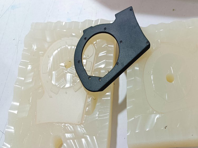
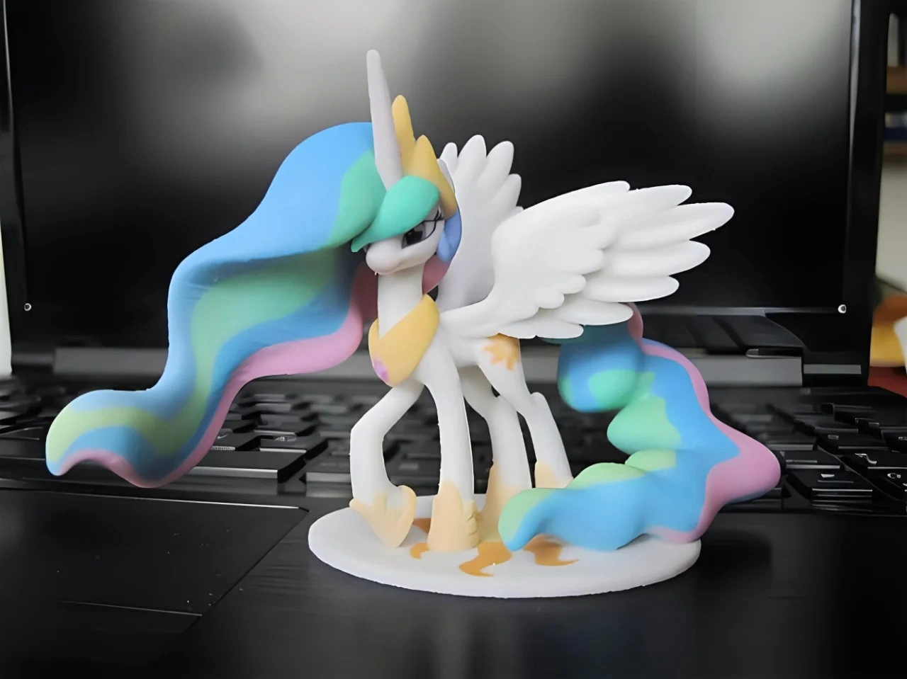
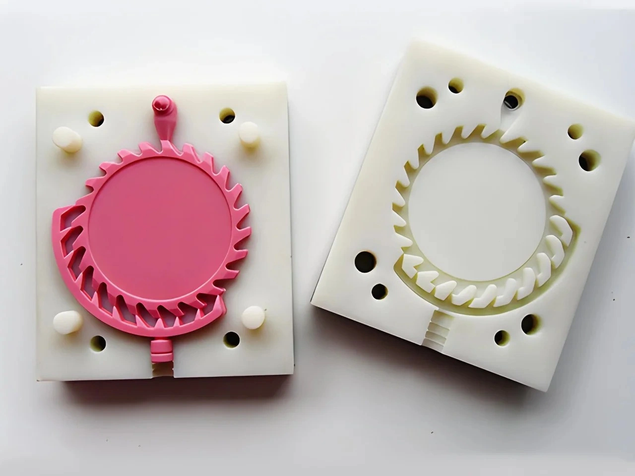
Neway supports the transition from urethane prototypes to mass production by recording approved geometry, interfaces, assembly findings, appearance intent and bounded test results, then giving the selected production process its own DFM, material specification, tooling design, samples and qualification plan. A smooth transition is managed through traceability and decision gates; it is not assured by a successful polyurethane part.
Transfer Map from Prototype to Production
| Urethane finding | Reusable product evidence | Production evidence to create |
|---|---|---|
| Assembly/fit result | Interfaces, access, sequence and gauge concepts | Production material deflection and process variation |
| Complex geometry trial | Envelope, routing and product-feature intent | Draft, splits, slides/cores, ejection and tool access |
| Dual-material prototype | Zone placement, tactile intent and interface concept | Production material compatibility and joining process |
| Appearance sample | Color, texture, gloss and cosmetic-zone priority | Tool texture, substrate preparation and finish-line capability |
| Bounded functional test | Design direction under stated conditions | Production material, process and qualification results |
Control the Prototype Record
Identify CAD/drawing revision, master and mold, polyurethane system, cure/conditioning, inserts, dual-material construction, finish, assembly state, test conditions, deviations and approvals. Link each accepted design change to the evidence that caused it.
List substitutions explicitly. A bonded insert, flexible silicone release, painted texture or polyurethane hardness may be useful for prototype learning without being the intended production construction. The record prevents a temporary workaround from becoming an unreviewed requirement.
Freeze Product Learning, Not Soft-Tool Assumptions
Use the urethane lot to close product questions such as connector access, gap, fastener location, grip zone, seal geometry and visual priority. Correct controlled CAD and drawings to reflect accepted changes.
Do not transfer silicone mold cuts, gates, vents or demolding deformation into a production tool. Those features belong to the prototype process. Product geometry that relied on silicone flex must receive a fresh production release review.
Select the Production Route from Service and Demand
Injection molding may fit thermoplastic parts requiring molded rate and resin-specific evidence. Die casting may fit metal geometry and demand where alloy, thermal flow and tooling economics agree. CNC may remain appropriate for low recurring demand or precision stock-material parts. The choice follows service load, environment, material, geometry, rate, cumulative demand and qualification.
A polyurethane prototype does not validate an aluminum, zinc, copper alloy or thermoplastic grade. Product engineering and the production supplier select and verify the exact material against the complete requirement set.
Repeat DFM for Injection Molding or Die Casting
Injection tooling needs draft, gates/runners, vents, cooling, ejection and potential slides/lifters. Die casting needs alloy flow, gates, overflows, vents/vacuum, thermal balance, ejection and trim. CNC needs stock, tool access, fixtures and setups. Each route creates different variation and surface evidence.
The production-transition review should disposition every undercut, thin/heavy section, insert, datum, cosmetic zone and material interface. Changes return to product engineering for approval.
Develop Production Tooling from Controlled Digital Data
Production tools are engineered from controlled CAD/drawings and process-specific analysis, not copied from the physical urethane part. A physical prototype can communicate assembly or appearance intent, but it cannot verify production mold flow, cooling stress or gate performance.
Tool design records cavity/core construction, parting, actions, ejection, thermal system, replaceable inserts, maintenance and ownership as applicable. Sampling then tests the real tool. Any shortcut from prototype geometry to tool manufacture must still preserve revision and DFM control.
Regenerate Material and Interface Evidence
Production resin or alloy samples repeat functional tests where material and process matter. For multi-material products, production adhesion, mechanical interlock, sealing and aging are verified using the intended materials and joining/overmolding route.
A urethane interface may guide zone geometry and test design. It cannot qualify thermoplastic overmolding, elastomer bonding, metal-to-polymer joining or long-term environmental exposure. Keep prototype and production results in separate traceable records.
Translate Appearance Intent with New Finish Samples
Preserve approved color, gloss, texture and cosmetic zones as intent references. Production substrate, cavity texture, flow, porosity and coating preparation can change appearance. Establish production limit samples from production-tool parts and the intended finish line.
The prototype-surface transfer plan should identify which visual attributes transfer and which process defects need new limits. Prototype paint approval does not qualify anodizing, powder coating or molded color on another substrate.
Release Tool Samples through Defined Gates
First tool samples are checked for controlled dimensions, assembly, appearance and process-created defects. The team compares them with prototype intent but also examines weld/flow lines, sink, porosity, ejection, trim, texture and coating behavior that urethane could not demonstrate.
Disposition each difference: adjust product geometry, tool, process, material, finish or acceptance standard. Repeat affected tests after change. A favorable small batch is evidence for that sampled state, not continuing mass-production capability by itself.
Build the Production Control Package
Release controlled CAD/drawing, material specification, DFM disposition, tool revision, critical characteristics, appearance standards, inspection/gauge plan, sample and qualification results, process/finish controls, packaging, deviations and change authority. Define resubmission triggers for tool, material, process or finish changes.
Demand and capacity plans should use accepted production output, not prototype mold output. Tool maintenance, cavity comparison, downstream finishing and inspection all belong in the production plan.
Transition RFQ and Decision Gates
Provide prototype records, approved product findings, unresolved risks, forecast/cadence, production material/process targets, service conditions, regulatory needs, critical interfaces, appearance and qualification tests. Ask for production DFM, tool concept, sampling sequence, finish route, validation, capacity and change control.
Neway supports a disciplined transition by keeping useful urethane learning traceable and requiring production-specific proof where it belongs. The result is fewer ambiguous assumptions at tooling release, not a claim that prototype success removes production development.