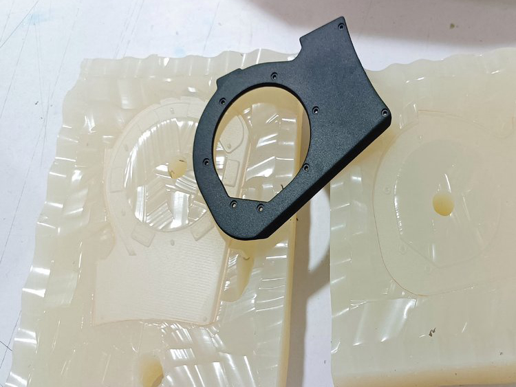
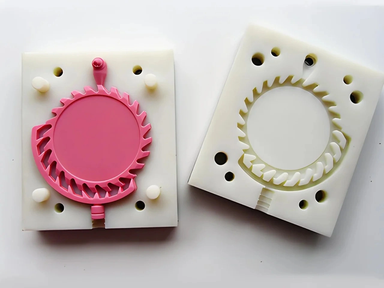
How does silicone mold casting support complex geometries?
Silicone mold casting supports complex geometry by combining a compliant mold wall with planned parting surfaces, cuts, loose cores and plugs. During demolding, the silicone can peel locally around selected undercuts instead of requiring every feature to follow one rigid draw direction. The geometry is feasible only if the mold and cured urethane can deform without tearing, locking, distorting or damaging an accepted surface.
Complexity Is Managed Through the Mold Concept
| Geometry challenge | Possible mold approach | Main failure mode | Approval evidence |
|---|---|---|---|
| External undercut | Local silicone peel | Tear at a sharp return or bent cast feature | Section and release direction |
| Side recess | Planned mold cut or split | Flash, cut witness or misalignment | Marked witness zone and first-off |
| Internal passage | Loose, rigid or sacrificial core | Core shift, leakage, deflection or lock | Core location/removal plan and internal check |
| Fine texture or lettering | Prepared master and compliant release | Master defect, trapped air or progressive detail damage | Physical reference and repeated inspection |
| Insert-bearing feature | Located insert cast into cavity | Insert movement, bubble or resin leak | Datum check and functional retention test |
Local Peeling Reduces Rigid Draw Constraints
A rigid one-piece tool must open along a direction that clears the part. Silicone can roll or peel away from a local feature, temporarily increasing the opening. That is why some negative-draft surfaces, grip textures and shallow hooks can be cast without a mechanical slide during prototyping.
The release load still passes through the silicone and the part. A large textured area can create substantial resistance. A thin rigid hook may crack before the mold clears it; a soft part may stretch and no longer represent the intended geometry. Review undercut depth, edge radius, surface area, part stiffness and the operator's access. Where possible, orient the release so silicone peels progressively rather than pulling a broad face at once.
Cuts and Splits Create Openings, Not Invisible Surfaces
After the silicone cures around the master, a planned cut may create a path to remove the master and later castings. Keys in the cut help realign the mold. A designed multi-piece mold can serve the same purpose for a geometry that needs repeatable access.
Every interface can leave a witness or flash. Cut edges may wear, tear or collect contamination. Put Class A surfaces, sealing lands and datums on the drawing, then agree where the split can appear and how trimming will be judged. If a witness crosses a functional face, change the mold plan, split the prototype into components or use an appropriate secondary operation.
Cores Need Location, Sealing and Removal
Internal channels are usually a core problem, not simply a flexibility problem. A core needs a defined support, a way to resist movement during filling, a sealed interface and a removal path. Long slender cores can deflect, while branched or reverse geometry can become trapped after cure.
A fully enclosed void cannot be created and then emptied by stretching the outside mold. It may require a sacrificial core, a bonded assembly or design revision. Each route changes internal surface, dimension, cleanliness and cost. For a functional passage, inspect continuity by sectioning, flow, visual access or another method suited to the risk.
Fill and Vent Access Matters as Much as Release
A geometry that can be demolded may still trap air or short-fill. High points, blind pockets, thin remote ribs and texture need a resin path and an air exit before the working time closes. Insert pockets and core junctions are common areas for bubbles or incomplete fill.
Ask the mold review to identify fill, vents and trim locations along with splits and cores. Inspect first-off parts for short fill, bubbles, voids, flash and distortion. Clear or sectioned sacrificial samples can make internal defects visible when the feature consequence justifies the extra work. Vacuum assists air management but does not replace geometry-specific venting.
Detail Transfer Starts with the Master
Liquid silicone conforms to the physical master, including intended texture and unwanted build lines, dust, sanding waves or repaired edges. Primer and paint can soften small lettering or sharp detail. The mold may reproduce an approved detail initially, yet repeated demolding can damage a vulnerable edge or cut.
Approve the master surface before mold construction and retain a physical texture or gloss reference. Decide whether logos are molded or applied later. Check detail across the build when it is an acceptance characteristic rather than assuming the first sample defines all later output.
Soft-Tool Feasibility Is Not Production-Tool Feasibility
A silicone mold can peel around an undercut that a steel injection tool would need to clear with draft, a slide, lifter or part redesign. A silicone cut does not determine a production parting line, gate or ejector location. Successful urethane casting therefore confirms a prototype route, not production manufacturability.
Maintain a list of prototype-only release features. Revisit them with the production resin, tool concept, expected rate and appearance requirements before hard-tool release. The silicone flexibility limit review provides a companion analysis of peel strain and repeated demolding.
Buyer Mold-Plan Checklist
Provide controlled CAD, critical sections, cosmetic and sealing surfaces, allowed witness locations, material or hardness target, insert data, quantity and intended production process. Request a marked mold concept showing split, cuts, keys, core pieces, insert locators, fill, vents, trim and demolding sequence.
Approve the first-off only after confirming cavity fill, acceptable release, mold condition, dimensions and witness surfaces. Continue checking the features that impose the highest peel or core load. The urethane casting process overview is useful context, but the actual geometry and acceptance criteria decide whether silicone mold casting supports the part.