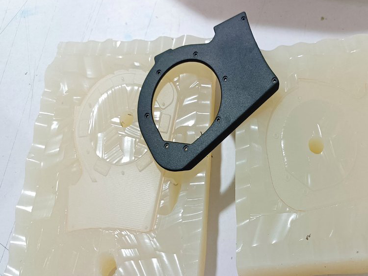
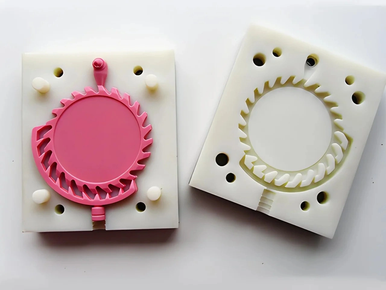
How does silicone mold flexibility support complex geometries?
Silicone mold flexibility supports complex geometry by deforming during demolding, so selected undercuts, re-entrant surfaces and textures can pass through a temporary opening after the urethane has cured. The mold may also use planned splits, knife cuts, loose cores and plugs. This expands prototype options compared with a rigid one-piece tool, but release still depends on undercut depth, section strength, peel path, surface finish and operator access.
What Flexibility Changes During Demolding
A rigid mold requires the part to move along an available draw direction unless mechanical actions withdraw from undercuts. Silicone can stretch and peel locally, allowing the mold surface to roll away from some features instead of forcing the entire part through a fixed opening. Peeling also reduces the instantaneous force compared with pulling a broad textured face straight out.
The useful motion is local and temporary. If the silicone must stretch too far, bridge a sharp edge or carry high tension through a thin section, it can tear or lose dimensional stability. The cured part can also fail first: thin hooks may bend, a narrow rib may crack, or a soft component may distort before release. Geometry must therefore be evaluated as a part-and-mold system, not as CAD volume alone.
Features That Often Benefit
| Feature | How silicone can help | Likely risk | Review evidence |
|---|---|---|---|
| Shallow external undercut | Local wall peels over the feature | Tear at a sharp return or witness on the surface | Section view and planned peel direction |
| Textured face | Compliant surface releases without rigid scraping | High release force over a large area | Texture reference, draft and release trial |
| Recess or side opening | Planned cut creates a temporary opening | Visible cut line and cut misalignment | Marked cut map and cosmetic-zone approval |
| Internal passage | Loose or sacrificial core may form the path | Core lock, movement, leakage or difficult removal | Core-removal sequence and section inspection |
| Embedded insert | Silicone seals around located hardware | Insert shift, resin leak or trapped air | Location fixture and pull/torque test |
Planned Cuts Are Engineering Features
A silicone mold may be cut after cure to create a parting path around a difficult master. A skilled cut can key the mold halves and place the witness in a hidden area. It is not invisible by default. Repeated opening, cleaning and alignment can change the cut edge, and thin flash may form where resin reaches the interface.
Buyers should mark Class A or customer-visible surfaces, sealing lands and measurement datums. The mold plan should show where a cut or parting line may appear and where trimming is allowed. Approve a first-off part before the remaining build. If a witness line crosses a sealing or optical surface, relocation, secondary finishing or a different part split may be needed.
Loose Cores and Enclosed Geometry
Internal channels and side holes may be formed with silicone cores, rigid inserts or removable plugs. The core needs a positive location, a way to resist buoyancy or casting pressure, and a removal path after cure. Long, slender cores can deflect. Complex cores can trap air or become locked by branches and reverse features.
A genuinely enclosed cavity cannot be formed and then emptied merely because the surrounding mold is flexible. It may need a multi-piece core, sacrificial element, bonded assembly or redesign. Each option changes surface condition, dimensional control and cost. Ask the supplier to describe the core material, locating features, sealing method and extraction sequence. Section an early sample or use an appropriate internal inspection method when passage continuity matters.
Filling and Venting Still Govern Results
Demoldable geometry is not automatically fillable geometry. Thin remote sections, high points and blind pockets can retain air. Resin viscosity, working time, vacuum practice, fill location and vent paths influence whether the cavity fills before cure advances. Thick-to-thin transitions may also respond differently during cure and cooling.
Review fill and vent marks together with the release plan. Put acceptable trim areas on the drawing and keep vents away from critical cosmetic or sealing surfaces where feasible. Inspect the first-off part for short fill, bubbles, voids, local sink, flash and distortion. A transparent sample or sectioned sacrificial part can help reveal internal fill quality, but the chosen method should match the actual risk.
Master Quality Sets the Starting Surface
Silicone reproduces the physical master and any subsequent mold defects; it does not improve an unfinished master automatically. Build lines, sanding waves, repaired edges and dust can become part of the mold surface. Fine detail may also be reduced by primer, paint or deliberate texture. The relevant benefit is controlled transfer, not perfect replication.
Approve the master at the surface state required for the mold. Use photographs and a physical texture or gloss reference. Decide whether logos and fine lettering should be present in the master or applied later. The urethane prototype surface guide explains how master preparation, mold condition and post-finishing combine to create the delivered appearance.
Why Prototype Release Does Not Prove Production DFM
A silicone mold can release a negative-draft feature by peeling. A steel injection mold cannot use that same motion without slides, lifters, collapsible cores or a design change. Likewise, a silicone cut line says nothing about where a production gate, ejector or cooling circuit belongs. Urethane casting can preserve product intent while the team evaluates the feature, but it cannot qualify production tooling around that feature.
Maintain two reviews: a prototype mold plan for making useful cast parts, and a production DFM review for the intended resin, tool and process. Mark every feature accepted only for prototype release. Before production-tool release, decide whether to add draft, split the component, add a side action or revise the geometry. This separation prevents a successful cast sample from becoming false evidence of easy production molding.
How to Approve Complex Geometry
Send controlled CAD, critical sections, cosmetic zones, permitted witness areas, material or hardness target, quantity and the intended production route. Request a marked review showing mold split, cuts, core pieces, insert locations, fill and vents, trim zones and demolding sequence. For severe undercuts, ask what is expected to flex: the silicone, the part or both.
Approve the first-off against four questions: did the cavity fill, did the part release without hidden damage, did the mold remain usable, and are witness marks acceptable? Repeat the check as the build progresses when the same feature imposes high peel load. Mold condition, not a generic shot count, should govern whether later parts remain acceptable.
Silicone flexibility is valuable because it provides controlled compliance where rigid tooling would need more elaborate actions. It is not permission to ignore locking geometry. The strongest design uses compliance, planned openings and inspection together, then carries every production-specific question into the later tooling review. For process context, see the urethane casting service overview.