What design factors should be considered before starting a urethane casting project?
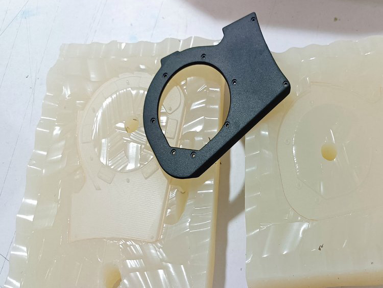
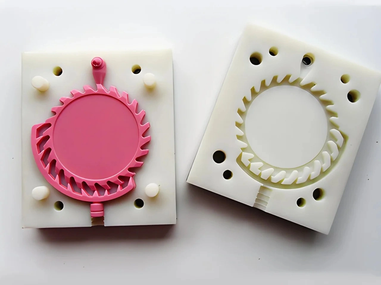
Before urethane casting, define what the prototype must prove and review the CAD for master production, silicone mold split, resin flow, air escape, demolding, wall behavior, inserts, trim access, cosmetic surfaces, critical dimensions and final testing. Flexible silicone expands design freedom but does not make every undercut, wall or tolerance easy. Release the design only after each functional feature has a manufacturing and verification route.
Design Review Matrix
| CAD feature | Process question | Failure risk | Release evidence |
|---|---|---|---|
| Undercut or return | Can silicone flex and the part exit safely? | Mold tear or part distortion | Demolding path and mold split |
| Thin/long wall | Can resin fill and the part stay stable? | Air, short fill or warpage | Flow/vent review and measurement state |
| Heavy section | Can cure heat and shrinkage be controlled? | Sink, void or local property difference | Resin/section review |
| Visible surface | Where are parting, gate, vent and repair marks allowed? | Unacceptable witness or texture mismatch | Appearance-zone drawing |
| Assembly interface | How is it located, finished and measured? | Fit failure after trim or paint | Datum and functional gauge |
Prototype Purpose Controls Every Other Choice
Separate appearance, assembly, ergonomics and functional tests. A photo sample may prioritize surface continuity; a connector trial prioritizes location and access; a flexible button trial prioritizes hardness, geometry and conditioning. Do not pay for controls that cannot change the current decision.
State the target production material and process, but identify which attributes the urethane part must simulate. This prevents a material nickname from becoming an unsupported performance specification.
Master Route and Source Surface
The master can be printed, machined or assembled. Its process affects accessible dimensions, supports, layer evidence, tool marks and repair. Silicone transfers the final master surface, so approve texture, gloss zones, edges and repairs before molding.
Apply compensation only after considering master, silicone and urethane behavior for the actual geometry. One global offset may not solve a flexible wall and rigid boss in the same way. Use first-casting results to refine feature-level control.
Parting and Demolding Must Be Planned Together
Locate splits where the mold can be made, opened and reassembled without damaging appearance or datums. A planned cut can release a complex feature, but it creates a witness and a sealing/reassembly task. Multi-piece molds or loose inserts may be preferable to excessive stretching.
Undercut depth, return shape, silicone thickness and extraction path matter more than a generic draft value. The flexible-mold geometry review should identify which features shorten mold life or require a design change.
Wall Distribution Affects Fill and Cure
Thin paths can trap air or stop filling; heavy masses can increase cure heat and local shrinkage. Abrupt transitions may produce visible sink, stress or property differences. Uniform walls are not mandatory, but every change should have a reason and a workable flow/cure route.
Use ribs, cores or assembled geometry only when they preserve the prototype question and can be produced repeatably. If a hollow region requires a removable core, define access and the seam or witness it creates.
Gate and Vent Location Affect Acceptance
Choose casting orientation so resin reaches thin and high regions while displaced air escapes. Gates must deliver material without leaving a trim scar on a critical face. Vents should be removable without erasing texture or weakening a fine edge.
Mark no-witness appearance zones and functional datums. A supplier can then place process features in lower-risk areas. First casting should confirm fill, air, trim and surface transfer before completing the lot.
Plan Inserts, Threads and Bonded Elements
Decide whether metal inserts, threaded hardware, magnets, windows or soft elements are cast in, bonded later or mechanically installed. Define locating, sealing, surface preparation and retention. Purchased hardware lead time belongs in the project schedule.
Protect threads, bond areas, connector seats and sealing surfaces during casting and finishing. The insert and secondary-machining review should connect each operation to a datum and inspection method.
Define Critical Dimensions and Measurement State
Identify fit, gap, connector, fastener and functional relationships. Use clear datums and state whether flexible parts are measured free, fixtured or assembled. Applying one tolerance to the whole casting can increase cost without improving the test.
Where assembly is the question, a functional gauge or mating component may provide more relevant evidence than isolated coordinates. Inspect after paint or bonding if those operations can change the interface.
Release Resin, Finish and Test Condition
Specify desired hardness, stiffness, flexibility, color, clarity or other bounded attribute and the evidence used to select resin. State cure/post-cure if applicable, part age and conditioning before test. Do not assume a demolded part is ready for final measurement.
Define molded texture, pigmented resin, paint, graphics and masked zones. Qualify coating compatibility with the exact urethane and cure state. Finish requirements can control both schedule and dimensional acceptance.
Urethane Design Release Checklist
Send controlled CAD/drawing, revision, prototype question, quantity, target attributes, master finish, parting constraints, appearance zones, critical dimensions, inserts, final finish, tests, reports, packaging and destination.
Request returned mold split/gates/vents, demolding plan, resin basis, compensation assumptions, first-part gate, trim/finish route, measurement state, technical deviations and remake triggers. A design is ready when process and evidence agree with its purpose.